Switchgear voltage transformer selection starts with the power-system connection and the functions that need a voltage signal. Specify the primary and secondary voltages, connection arrangement, insulation requirements, accuracy duty, connected burden, protection interfaces and installation conditions together. A ratio alone cannot establish compatibility with a relay scheme or an existing switchgear assembly. This guide focuses on conventional inductive voltage transformers used for measurement and protection inside medium-voltage projects. Capacitive devices, low-power sensors and other technologies require their own verified application data and interface rules.
Define the measurement point before choosing equipment
Identify whether the voltage signal represents a bus section, incoming feeder, outgoing circuit or another designated point. This determines which operating conditions the signal can describe. A bus-side VT and a feeder-side VT can report different conditions when switching devices are open. Show the measurement point on the single-line diagram and carry the same identifier into the secondary schematic and protection study.
List the consumers of each secondary winding, including meters, protection relays, synchronism-check functions and supervisory equipment where applicable. Assign an owner to each function. Without this functional register, a supplier may offer a transformer that meets a nominal ratio while leaving an important protection or operating interface undefined. Avoid adding spare consumers later without reassessing the agreed design.
Distinguish system voltage from winding connection
State the system nominal voltage and applicable highest voltage for equipment separately. Then identify whether each primary winding is connected phase-to-earth or phase-to-phase. The rating notation must agree with that arrangement. An engineer reviewing a three-phase system should not assume that every winding sees the line-to-line voltage. The same distinction applies when reading secondary ratings and connected relay inputs.
The system earthing arrangement also matters. Ask the responsible engineer to establish the voltage duty during the relevant earth-fault conditions and how that affects the offered VT specification. This article does not prescribe a universal voltage factor or duration because those requirements depend on the system and governing specification. The quotation should state the selected values and their application basis explicitly.
Use the correct document scope
IEC 61869-3 addresses inductive voltage transformers for measuring and protective applications. Its published scope helps identify the equipment family, but the catalogue summary is not a substitute for the complete applicable requirements. Confirm the contract edition, national adoption and any project-specific additions. The switchgear assembly requirements and the instrument-transformer requirements form related but distinct parts of the evidence package.
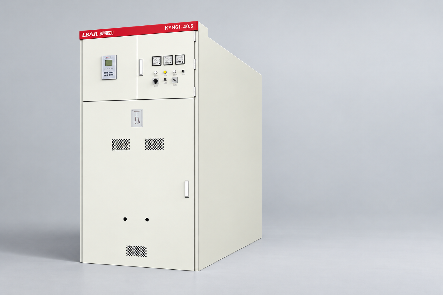
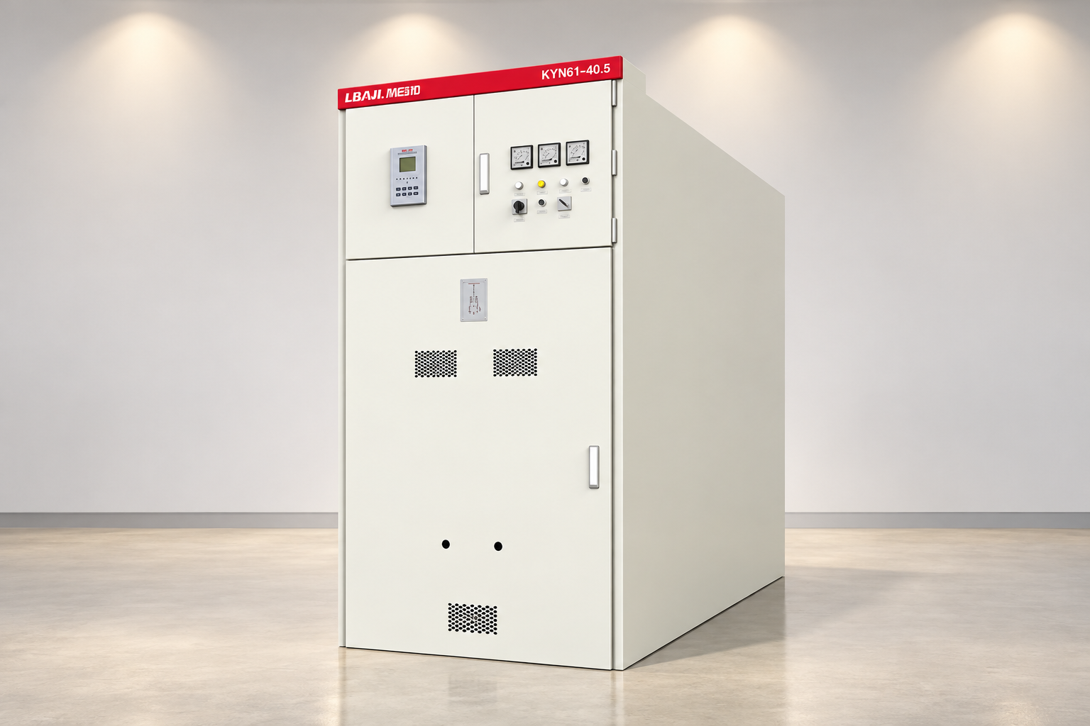
A catalogue photograph of an LBAJI KYN61 enclosure does not reveal the internal VT arrangement. Request the offered project component schedule, primary arrangement and wiring documents. Treat the illustrated cabinet as the assembly context. Do not infer a particular voltage ratio, accuracy class or removable VT truck from an exterior image or from the ratings of another assembly in the same product family.
Prepare a specification matrix
سياق المراجع: IEC 61869-3 inductive voltage-transformer scope. تُعد هذه القائمة المرجعية النوعية الأصلية منظمةً للقرارات المتعلقة بالمشروع؛ وهي ليست معيارًا مُعاد تصنيفه أو بديلًا للمعايير المعتمدة.
| Selection field | Required project evidence | Common omission to prevent |
|---|---|---|
| Measurement point | Single-line diagram with identified bus or feeder location | Assuming one voltage signal represents every switching state |
| Primary connection | System voltage, earthing arrangement and winding connection | Confusing phase-to-earth and phase-to-phase ratings |
| Secondary windings | Ratios, functions, terminals and connected devices | Treating all windings as interchangeable |
| Accuracy and burden | Required class and supported operating burden range | Choosing only a large VA number |
| Secondary interfaces | Schematics, protection, earthing and test arrangements | Missing a fuse, link or external circuit boundary |
| Installation evidence | Assembly drawings, access and verified service conditions | Assuming a physically similar component is a direct replacement |
Use this table as a document checklist rather than a list of fixed technical values. The responsible engineer must populate the project requirements. A supplier response should indicate compliance, proposed deviations and any unavailable data. Where an item is unresolved, retain a visible hold point instead of filling the cell with an assumption that nobody has accepted.
Match secondary voltages to the receiving devices
Collect the exact voltage-input options of every meter and relay. Check whether the devices expect phase-to-neutral or phase-to-phase quantities and how their settings interpret the ratio. A receiving device can display an apparently plausible value while its scaling or connection assumptions are wrong. Drawings, device settings and test records need to describe the same measurement chain.
Separate measurement windings from any winding intended for residual-voltage or other protection functions. Where a residual-voltage scheme is required, the connection and associated equipment must follow the approved design. Do not improvise a secondary interconnection from a general online diagram. The specification should show the functional purpose, terminal identification and responsible design authority for each circuit.
Evaluate burden and accuracy as a complete circuit
Sum the connected inputs using their supported data and the applicable connection model. Include the effect of secondary wiring where relevant to the accuracy assessment. The total connected VA, its power factor and the expected operating range should be compared with the offered guarantees. The highest rated output on a catalogue page is not automatically the best accuracy match for a lightly loaded digital circuit.
Secondary conductor voltage drop can affect the signal delivered to remote equipment. Evaluate it for the actual route, connected load and function instead of assuming that a satisfactory transformer nameplate resolves the entire measuring chain. Revenue metering, protection and operational indication can have different accuracy responsibilities. Document where the guaranteed measurement boundary ends and who verifies the downstream circuit.
Specify secondary protection and earthing interfaces
Voltage-transformer secondary circuits require their own approved protection and isolation arrangements. Their behaviour differs from a conventional CT secondary circuit, so CT shorting practices must not be transferred to VTs. The schematic must identify protective devices, test facilities and circuit boundaries appropriate to the application. General component familiarity does not authorize a technician to alter the installed circuit.
Define secondary earthing through the approved design and installation documentation. Multiple unintended earth connections or a missing intended reference can create measurement and safety problems. The commissioning record should verify the actual arrangement without turning this article into a live-work procedure. Work must be performed by qualified personnel using suitable isolation, verification and risk controls for the real installation.
Consider abnormal conditions and operating sequences
Ask the system designer to review energization, switching, abnormal voltage conditions and relevant interaction with the network. Where ferroresonance is a credible concern, obtain a documented application assessment and any manufacturer-approved mitigation. Do not add a generic resistor or other damping component merely because a similar arrangement appears in another project. Its rating and connection require an engineering basis.
Review how loss of a VT signal is detected and how affected protection or control functions respond. This includes the distinction between an actual system voltage condition and a failed secondary circuit. The required supervision, blocking or alarm logic belongs in the approved scheme documents. Record the expected behaviour so that functional tests can verify the intended response later.

Check assembly integration and access
Verify component dimensions, mounting, insulation coordination and all primary and secondary interfaces against the actual assembly design. If the VT arrangement is removable, its positioning, interlocking and access provisions must be supported by the offered design. Physical fit alone does not demonstrate compatibility. Changes can affect dielectric clearances, wiring, operating procedures and existing verification evidence.
For replacement work, collect the installed component identification, drawings and available original documentation before asking for an alternative. A new device with a similar front view or ratio may have different terminal positions, winding duties or protective arrangements. Ask the supplier to identify every consequential change and provide the required assembly-level review rather than treating replacement as an isolated catalogue purchase.
Define useful factory and site records
The inspection and test plan should distinguish component evidence from assembly wiring and functional verification. Request the applicable VT identification, ratings, ratio and polarity records together with the required assembly documents. At site, compare the supplied equipment and connections with the approved drawings. Any planned electrical tests need a method that protects connected electronic equipment and respects the manufacturer’s instructions.
Functional verification should confirm the signals delivered to the designated devices, including scaling, phase association and relevant supervisory behaviour. Record the test boundary, instruments, results and acceptance basis. A relay screen showing voltage is not a complete acceptance record. It does not independently establish correct phase association, winding assignment or behaviour when a secondary protection device operates.
Create a quotation and handover package
Provide the supplier with the single-line diagram, system earthing information, voltage duties, secondary function register, device input data, route information and installation conditions. Ask for an annotated response tied to the actual offered component and assembly. Separate confirmed values from assumptions. The purchaser can then compare proposals without hiding a technical deviation inside a short commercial description.
At handover, retain the approved specification, as-built drawings, component identification, relevant test results and receiving-device settings. Identify the checks required when a winding gains another load or a relay is replaced. This makes future work repeatable and helps prevent a secondary modification from undermining the measurement or protection assumptions accepted during the original project.
الأسئلة الشائعة
Is a VT ratio enough to select switchgear equipment?
No. The connection, system earthing, insulation duty, winding functions, accuracy, burden and assembly interfaces must also suit the project.
Can a phase-to-earth rating be treated as phase-to-phase?
No. Read the rating with the actual winding connection and system arrangement. The specification and receiving-device settings must use consistent quantities.
Does a higher rated burden always improve accuracy?
No. Compare the actual circuit burden and operating range with the offered accuracy guarantees. A larger catalogue VA value alone does not establish the best application.
Can CT secondary practices be used for VT circuits?
No. Conventional CT and VT circuits have different characteristics. Use the approved VT protection, isolation, earthing and test arrangements for the installation.
What should accompany a replacement VT enquiry?
Supply the installed identification, drawings, winding duties, connected-device data and assembly information. Ask the supplier to document compatibility and any resulting design changes.
المصادر التقنية والمعدات ذات الصلة
تقوم صفحات الكتالوج القياسية بوضع نطاق الوثيقة؛ ويقتضي الامتثال والقبول استعراض الوثائق الكاملة المعمول بها ومراجعة هندسة المشروع.
- IEC 61869-3 inductive voltage-transformer scope
- NPTEL current and voltage transformers
- UK HSE HSG85: Electricity at work, safe working practices
- LBAJI KYN61-40.5 معدات التجهيز الكهربائي القابلة للإزالة مع المكونات المعدنية
- أساسيات معدات التبديل
- تحقق وتجربة المعدات الكهربائية
- potential-transformer fundamentals
التعلم الإضافي: الخلفية الفنية
This independent educational video explains the measurement principles or equipment background discussed above. It does not demonstrate a safe work procedure for the specific assembly. Source: NPTEL IIT Kharagpur.
Watch Lecture 42: Current transformer and potential transformer