ال voltage drop formula for a single-phase circuit must include the complete outgoing and return conductor path. For equal conductors and a steady sinusoidal lagging load, a common approximation is ΔV ≈ 2IL(R cos φ + X sin φ). Here L is the one-way cable length, I is current, and R and X are conductor resistance and reactance per unit length. For a nearly resistive load with negligible reactance, this reduces to ΔV ≈ 2ILR. Neither expression selects a safe conductor size by itself: temperature, installation conditions, protection and the permitted load-terminal voltage require separate checks.
Choose the Circuit Boundary Before Calculating
Start with the actual supply and load terminals. A single-phase circuit can operate between a line and neutral or between two lines. In either arrangement, load current passes through two conductors. The protective earth is not the normal return conductor and must not be included as though it carries operating current. Identify which conductors form the working loop on the approved drawing.
The circuit boundary also determines whether an upstream feeder must be included. A calculation beginning at a branch distribution board excludes the voltage loss between the transformer and that board. If the equipment specification concerns voltage at the final load, review every relevant segment from the agreed source. Keep each segment’s length, current and impedance separate, particularly when other loads join along the route.
The Single-Phase Formula and Its Units
The following expressions are steady-load approximations. The circuit model follows the Electrical Installation Guide voltage-drop calculation. Use the cable manufacturer’s impedance data for the actual conductor construction and operating temperature. The worked example below uses explicitly hypothetical inputs, not product specifications.
| حساب | Expression | Meaning and limitation |
|---|---|---|
| Single-phase, equal outgoing and return conductors | ΔV ≈ 2IL(R cos φ + X sin φ) | L is one-way length; R and X are values for one conductor per unit length; φ follows the lagging-load convention. |
| Nearly resistive load, reactance negligible | ΔV ≈ 2ILR | Do not assume this simplification applies to long motor feeders or arbitrary nonlinear loads. |
| Using an already calculated loop resistance | ΔV ≈ I Rloop | Rloop includes both conductors. Do not multiply by two again. |
| Percentage voltage drop | ΔV% = 100ΔV / Vreference | Use the applicable single-phase supply voltage at the calculation boundary. |
If R and X are expressed in ohms per kilometre, put L in kilometres. If they are expressed in ohms per metre, put L in metres. Current is in amperes and the resulting voltage drop is in volts. A factor-of-one-thousand mistake can look plausible when a worksheet hides the units, so write the units beside every input. Do not mix cable resistance with a load resistor’s resistance.
Why the Return Path Matters
Consider a source connected to a load by a fifty-metre route. The current travels fifty metres outward and fifty metres back, so the equal-conductor loop contains one hundred metres of conductor. The factor of two in the simplified formula accounts for that loop. Entering one hundred metres and still multiplying by two counts the return path twice.
If the outgoing and return conductors have different sizes or materials, calculate their impedances separately. Connections and additional circuit segments can also contribute impedance. A simple equal-conductor formula cannot represent every arrangement. An engineer should establish the appropriate model where parallel conductors, shared neutrals or substantial imbalance affect the return path.
Worked Example With Clearly Stated Assumptions
Suppose a hypothetical single-phase resistive load draws 20 A from a 230 V source. The one-way route is 50 m. Assume equal outgoing and return conductors, a resistance of 1.0 Ω/km for each conductor at the selected calculation temperature, and negligible reactance. These values demonstrate the arithmetic; they do not identify a recommended cable or an LBAJI equipment rating.
Convert 50 m to 0.050 km. The loop resistance is 2 × 0.050 × 1.0 = 0.100 Ω. Therefore the approximate drop is 20 × 0.100 = 2.0 V. Relative to the assumed 230 V source, the percentage is 100 × 2.0 / 230 ≈ 0.87%. The estimated load voltage is approximately 228 V under the same steady operating conditions.
To assess the result, compare it with the equipment’s required terminal-voltage range and the applicable project limit. An acceptable percentage does not prove cable ampacity, short-circuit withstand, protective-device coordination or termination suitability. Those decisions need their own calculations and verified installation information.
Include Power Factor and Reactance When They Matter
For a sinusoidal lagging load, cos φ represents displacement power factor. The reactive term X sin φ accounts for the component associated with conductor reactance. A motor’s starting and running conditions differ, so a worksheet using normal operating current cannot establish starting voltage. Obtain the current and power-factor information for the operating condition being evaluated.
True power factor and displacement power factor can differ for drives, rectifiers and other nonlinear equipment. Substituting a total-power-factor reading into a simple sinusoidal expression does not automatically account for harmonic voltage drops. Where waveform distortion matters, use an appropriate power-quality and network model. State whether each input was measured, supplied by the manufacturer or assumed.
Use Temperature-Appropriate Cable Resistance
Resistance changes with conductor temperature. Catalogue values may describe a reference temperature rather than the operating condition expected in the installation. Check the data basis before comparing calculations. Material, conductor size, construction and connections also affect the resistance used in the circuit model.
A design worksheet should retain the cable data source and the reason for the selected temperature. Avoid treating a room-temperature measurement on an isolated cable as the final resistance under sustained full load. Conversely, do not invent a temperature correction when the supplier has already provided the required operating-temperature value. Keeping the data basis visible prevents double correction.
Add Feeder Segments Without Double Counting
A final load may receive power through a transformer, a main switchboard, a distribution board and a branch circuit. Record the current flowing in each section under the selected load case. The main feeder may carry several loads while the branch carries only one. Applying the branch current to the entire route can understate the upstream loss.
For simple compatible steady conditions, individual cable-drop estimates can support a total route assessment. More complex networks require phasor treatment and the actual upstream source model. Transformer regulation, supply variation and transient events are separate from cable voltage drop. Document them separately so the load-terminal assessment does not omit or double count a contribution.
Review the Distribution Equipment Interface
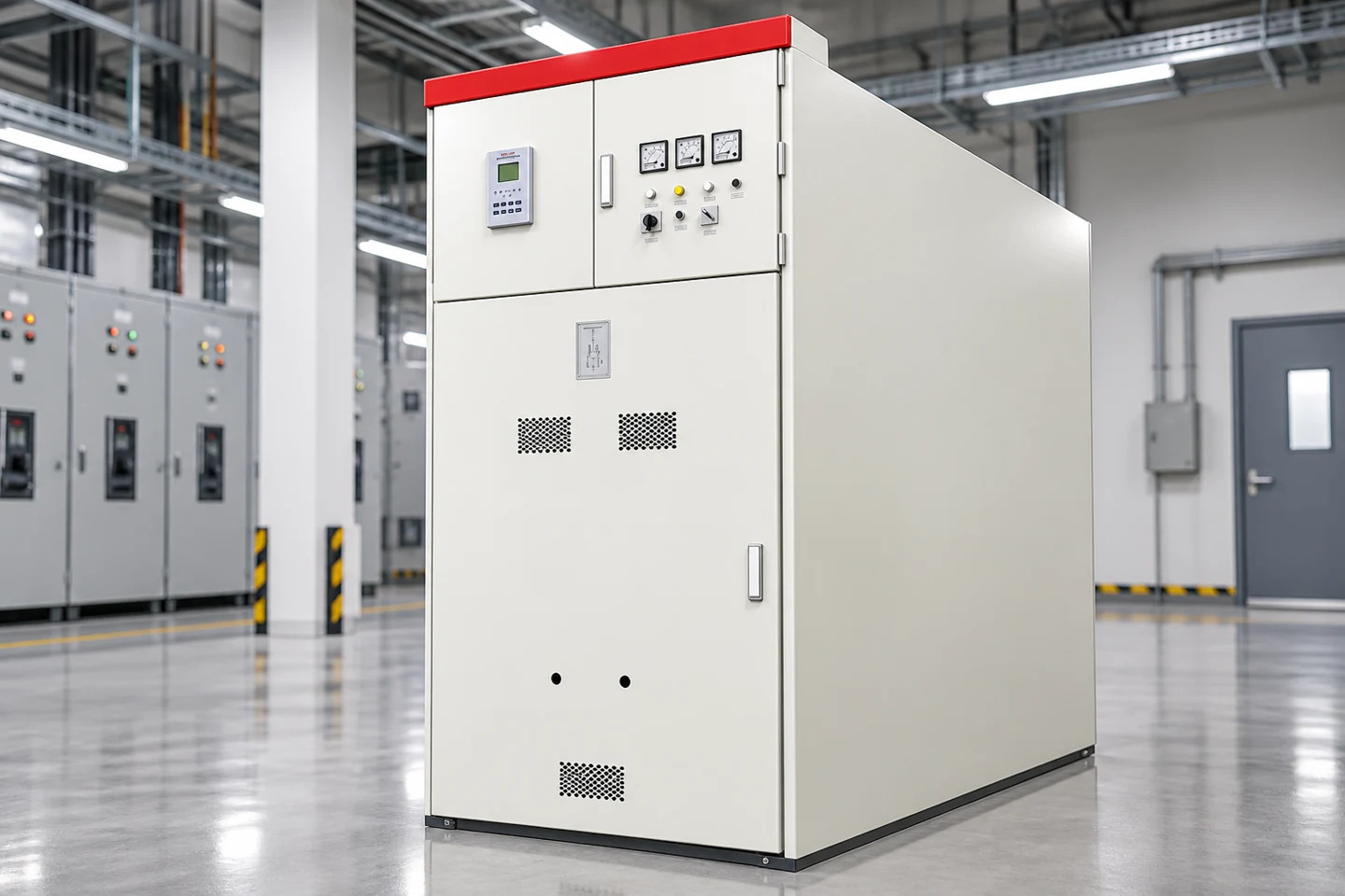
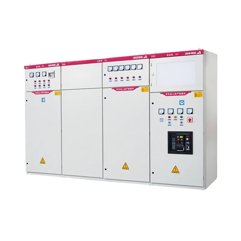
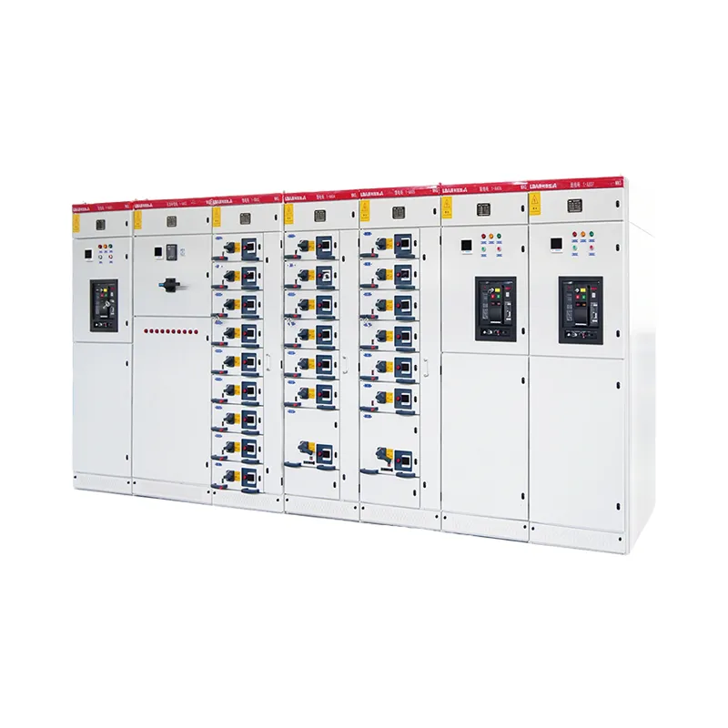
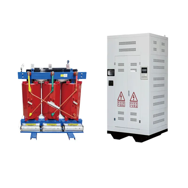
The cable calculation concerns the connection between equipment, while the distribution assembly must be selected for its own electrical and environmental duties. Review the خزانة مفاتيح الجهد المنخفض من نوع GGD equipment context when planning low-voltage distribution. A cabinet photograph does not establish conductor impedance or an allowable voltage-drop percentage.
For related calculations, distinguish the inputs used in حسابات المحولات ثلاثية الأطوار و حسابات الأمبير إلى كيلو فولت أمبير. The allowable voltage-drop discussion addresses a separate question: the limit applicable to the installation. A correct formula and a correct acceptance criterion are both necessary.
Measure and Investigate Under a Defined Load
When commissioning requires measurements, record the supply voltage and load-terminal voltage under comparable load conditions. Changes in the supply between readings can obscure the cable contribution. Include the current, load state, instrument configuration and measurement time. A single unloaded voltage reading cannot demonstrate performance during normal operation or a motor start.
Measurements on electrical equipment require qualified personnel, appropriately rated instruments and the site’s safe-work procedure. Use the site-specific safe-work method and governing requirements before connecting instruments. The NIST electric-current unit reference supports consistent use of amperes; it is not an electrical-work procedure. De-energized resistance tests and energized voltage measurements are different activities with different controls.
Common Worksheet Errors
The most frequent arithmetic error is counting the return conductor incorrectly. Other problems include metres entered against ohms per kilometre, the wrong reference voltage, resistance at an unsuitable temperature, and current from a different operating condition. Record the circuit arrangement and units before entering numbers, rather than relying on a calculator’s default settings.
Do not use the balanced three-phase factor √3 for a single-phase two-wire circuit. Do not substitute a resistor’s voltage division for cable loss. Do not treat a conductor chosen for a low percentage drop as automatically protected against faults. A useful review checks the electrical model first, the arithmetic second and the engineering acceptance criteria last.
Calculation and Procurement Record
Keep the route length, conductor material and size, impedance data, temperature basis, load current, voltage reference and operating condition together. Include the calculated volts and percentage, the source of the applicable limit, and the load manufacturer’s voltage requirement. Where a revision changes the route or load, repeat the relevant assessment and preserve the earlier version for traceability.
For an equipment enquiry, provide the distribution drawing, source arrangement, expected load profile, installation environment and protection requirements. Explain which calculations concern the assembly and which concern external cables. This allows the supplier and project engineer to discuss the correct interface without implying that a generic enclosure catalogue validates the whole circuit.
Educational Video: Resistance in a Series Path
The Wisc-Online lesson below explains basic voltage division in a series circuit. It supports the resistive-loop concept only; it does not cover AC cable reactance, installation limits or conductor selection. Use the circuit-specific expressions above for the feeder calculation.
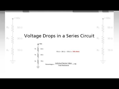
Watch the Wisc-Online series-circuit lesson.
Why is there a factor of two in the single-phase formula?
It accounts for equal outgoing and return conductors when length is entered as the one-way route. A loop resistance that already includes both conductors must not be doubled again.
Can I always use voltage drop equals current times resistance?
That approximation applies to a suitable resistive loop. AC load angle and conductor reactance may require the fuller circuit expression.
Which voltage belongs in the percentage calculation?
Use the applicable single-phase supply voltage at the defined calculation boundary, whether the load operates line-to-neutral or line-to-line.
Does low calculated voltage drop prove a cable is safe?
No. Ampacity, protection, fault withstand, installation conditions and load-terminal requirements need separate verification.
Should I calculate motor starting separately?
Yes. Starting current, load angle and upstream supply behavior differ from normal operation and can create a different terminal-voltage condition.
For the resistance-only starting point, see OpenStax: Ohm’s law. Apply it to the conductor loop rather than confusing cable resistance with load resistance.