A vacuum interrupter integrity test evaluates a defined aspect of the interrupter’s dielectric or vacuum condition using an approved method and acceptance basis. It must be distinguished from a general switchgear insulation test, contact resistance measurement and mechanical operating check. For buyers and maintenance teams, the essential questions are what the method actually demonstrates, which interrupter model it applies to and how the result supports an engineering decision. A passed test under one set of conditions is useful evidence, but it is not an unrestricted guarantee of future interruption performance.
Start with the interrupter and its function
A vacuum circuit breaker interrupts current within sealed interrupters, while the surrounding assembly provides additional insulation, supports, conductors, operating mechanisms and enclosure functions. The condition of these different elements is related but cannot be reduced to one reading. A problem outside the interrupter can affect a dielectric test without necessarily proving a loss of internal vacuum.
Identify the breaker model, interrupter designation, serial information and supplied documentation before selecting a method. If an interrupter is embedded or partly concealed, its external appearance may reveal little about its condition. The front of an enclosed cabinet is even less informative. Obtain the actual equipment records rather than inferring the interrupter design from a catalogue photograph.
Define what the proposed test demonstrates
Different methods assess different physical quantities. An approved withstand test checks behavior under specified electrical stress and conditions. A specialized vacuum-condition method may assess another characteristic using its own instrument and interpretation requirements. Neither label should be used casually as a synonym for all possible integrity checks.
The test schedule must name the method and state the claimed conclusion. Ask whether the result applies to an individual interrupter, a complete pole or the assembled breaker. State any limitations associated with connected components, surface condition or test configuration. This is especially important when comparing a factory report with a later field test performed through a different insulation path.
Use model-specific instructions rather than a generic test voltage
The suitable test arrangement, voltage waveform, magnitude, duration and acceptance criteria depend on the supplied equipment and approved procedure. An online example for another breaker is not sufficient. Using an inappropriate method can produce misleading results or damage equipment that was previously serviceable.
Ask the manufacturer or responsible engineer to identify the exact applicable instructions. Confirm the document revision and any restrictions on particular test instruments or waveforms. If the equipment history or interrupter identity is uncertain, resolve that uncertainty before testing. An incomplete record should lead to a documented hold point, rather than a guessed test setting.
Control electrical and stored-energy hazards
Integrity testing can involve hazardous electrical energy even when the primary circuit is out of service. Qualified personnel need an authorized isolation and test plan covering primary and auxiliary circuits, stored energy, access restrictions and the test instrument itself. Appropriate discharge and restoration controls must follow the supplied instructions.
Some vacuum interrupter test conditions can present additional hazards that require manufacturer guidance, including precautions associated with high-voltage testing. This article does not establish safe distances, test voltages or a work sequence. The test organization must apply the relevant equipment and instrument requirements and account for the actual site arrangement before authorizing work.
Separate internal condition from external insulation condition
A complete breaker includes external insulating surfaces and clearances as well as the sealed interrupter. Contamination, moisture, damaged insulation or an unintended test path can influence an observed result. An abnormal complete-pole test must therefore be investigated within its defined boundary rather than immediately described as a failed vacuum bottle.
Record the equipment state, inspection findings and relevant environmental conditions. If the approved procedure requires cleaning or another preparation step, document what was done and retain the original observation. Do not apply unapproved cleaning agents, coatings or mechanical intervention to an interrupter or embedded pole. Surface treatment and material compatibility are equipment-specific matters.
Referenzkontext: IEC 62271-100 alternating-current circuit-breaker scope. Diese ursprüngliche qualitative Checkliste organisiert die Projektentscheidungen; sie ist keine reproduzierten Standardformel oder ein Ersatz für genehmigte Kriterien.
| Evidence item | Useful question | What it does not establish alone |
|---|---|---|
| Interrupter identity | Which supplied design is being assessed? | Current internal condition |
| Approved dielectric test | Does the defined path meet the specified test criterion? | Every aspect of future switching performance |
| Specialized vacuum assessment | What condition does this method indicate for this model? | Suitability of unrelated methods or limits |
| Mechanical operation record | Does the mechanism move as required? | Internal vacuum condition |
| Contact resistance record | Is the defined conductive path consistent with its criteria? | Dielectric integrity |
| Engineering review | How do all findings affect service readiness? | Permission to ignore unresolved exceptions |
Understand the limits of visual inspection
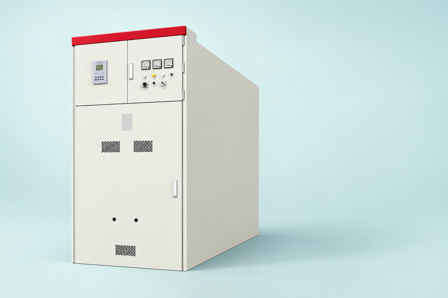
Visual inspection remains useful for obvious damage, contamination, missing parts and identification, but it cannot establish a vacuum condition simply because the exterior looks clean. A sealed or embedded design may conceal the relevant internal condition completely. Likewise, a changed external color or mark should be assessed against the actual manufacturer instructions rather than an unrelated photograph.
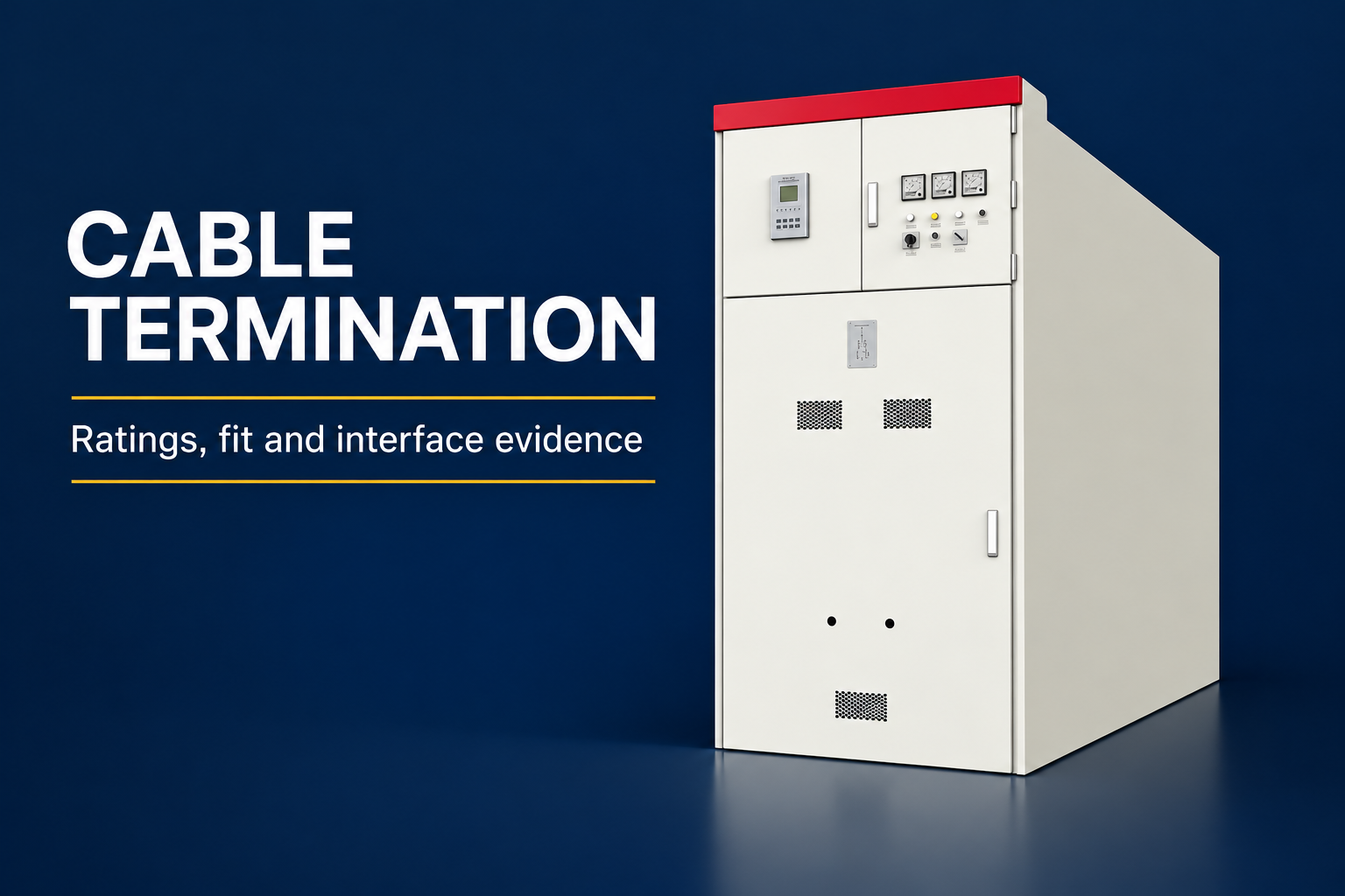
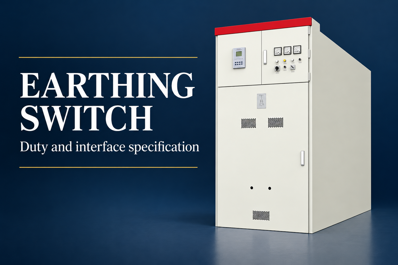
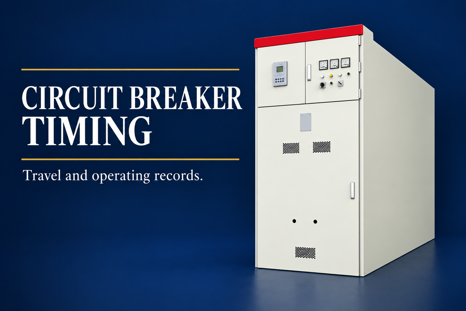
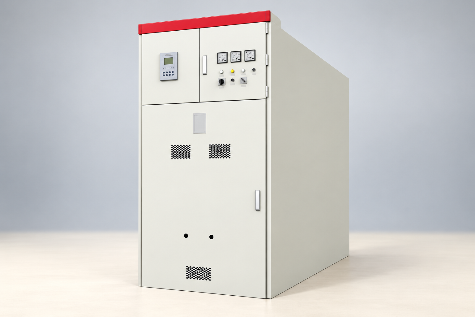
For an LBAJI KYN61 assembly, the product reference illustrates the enclosure family and visible access arrangement. It does not depict an exposed interrupter or a test setup. Request the project breaker data, internal arrangement and relevant reports if interrupter-specific evidence is needed. Keeping these boundaries clear prevents a product image from being mistaken for technical proof.
Compare repeated tests only when the methods match
A historical result is valuable when its test method, equipment state and assessment basis are available. The same descriptive test name may conceal differences in voltage waveform, connection boundary or instrument behavior. Review those differences before interpreting a change as deterioration or improvement.
Retain the raw result, instrument identification, applicable calibration record and any associated observations. If a test is repeated after a setup correction or approved preparation, link the new result to the original and explain the change. A report containing only the final preferred outcome cannot support a reliable trend or a later investigation.
Investigate an abnormal result without overclaiming
Begin by confirming that the method was applicable and the test arrangement followed the approved procedure. Review connections, equipment identification, external insulation condition and the instrument record. A persistent abnormal result requires the responsible engineer and manufacturer to determine further investigation, restrictions or replacement action.
Do not repeatedly apply electrical stress in the hope that the result will improve. Repetition itself needs a defined purpose and authorization. Avoid declaring either a vacuum failure or a harmless test artifact before the evidence supports that conclusion. The report can state that the result is unresolved and identify the next required evidence without pretending to provide a diagnosis.

Distinguish maintenance checks from design qualification
A field integrity check is not a complete type-test program. A breaker design’s making and breaking duties, mechanical endurance and other characteristics require their own applicable qualification evidence. A successful maintenance test on one interrupter cannot create a missing design rating or prove compatibility with a different mechanism.
Similarly, a type-test report for a related design must be reviewed for applicability to the supplied breaker. Identify any design differences and obtain the manufacturer’s explanation of coverage. Procurement acceptance should connect the report to the delivered equipment configuration rather than treating a familiar standard number on a certificate as sufficient evidence.
Request a useful supplier test package
A purchase specification should state the required evidence and review points without prescribing an unsupported test method. Ask for the interrupter and breaker designations, applicable instructions, test boundaries, acceptance basis and deviation process. Identify whether the purchaser expects factory witness access or a report review before shipment.
For replacement poles or interrupters, request documented compatibility with the original breaker and mechanism. Mechanical fit alone does not establish electrical or operating compatibility. Update equipment identity, maintenance instructions and baseline records after an authorized replacement. Preserve the history so that a later team can distinguish original and replacement components reliably.
Combine integrity evidence with the overall readiness decision
An interrupter assessment belongs within a broader equipment evaluation that may include mechanical operation, contact condition, insulation, control circuits, protection and interlocking. The final readiness decision must address the complete commissioning or maintenance requirements. No single test should close unrelated defects or missing documentation.
Where the evidence is incomplete, define the restriction and next action clearly. A pending engineering review is different from an accepted result, and an accepted individual test is different from authorization to energize the assembly. This separation helps operating teams understand what they can rely on and what remains unresolved.
Preserve the final condition and follow-up record
After testing, complete the approved discharge, restoration and handover process. Record the final equipment state, removed temporary connections, report references and any remaining restrictions. The responsible reviewer should sign off the actual scope completed, including deviations and any required reinspection.
A useful maintenance record is understandable years later. It identifies the equipment, method, conditions, result and decision without depending on the memory of the original test team. That documentation turns an isolated integrity check into a reliable part of the asset’s history and supports more informed procurement, maintenance and replacement decisions.
Häufig gestellte Fragen
Is a vacuum interrupter integrity test the same as a switchgear insulation test?
No. The measurement boundary and method can differ. A complete assembly test may include external insulation and other components, while an interrupter-specific method has its own defined scope.
Can a clean exterior prove that the interrupter retains vacuum?
No. Visual inspection can identify external condition and damage but does not establish internal vacuum condition. Use an applicable approved method and the supplied equipment instructions.
Can a test voltage from another breaker be reused?
Do not assume that it is suitable. Obtain the correct method, waveform, magnitude, duration and acceptance criteria for the actual supplied design and test arrangement.
Does a passed integrity check prove fault interruption capability?
It provides evidence within its defined scope. Rated making and breaking performance, design qualification and the complete readiness assessment require separate applicable evidence.
What should happen after an abnormal result?
Preserve the result, verify method and setup, review external condition and obtain engineering and manufacturer direction. Do not repeatedly stress or alter the equipment without an authorized investigation plan.
Technische Quellen und damit verbundene Ausrüstung
Standardkatalogseiten legen den Dokumentenbereich fest; die Einhaltung und Annahme erfordern die vollständigen Dokumente und eine Projektüberprüfung.
- IEC 62271-100 alternating-current circuit-breaker scope
- CIGRE technical webinar: fundamentals of current interruption in vacuum circuit breakers
- UK HSE HSG85: Electricity at work, safe working practices
- LBAJI KYN61-40.5 Armierungsmaterial für abnehmbaren AC-Schaltgeräteschrank aus Metall
- Grundlagen der Schaltanlagen-Ausrüstung
- Überprüfung und Prüfung der Schaltanlagen
- switchgear thermal inspection evidence
Weiterbildung: technisches Hintergrundwissen
Dieses unabhängige Bildungsvideo erklärt die oben erwähnten Messprinzipien bzw. die Hintergrundinformationen zu den Geräten. Es zeigt jedoch keine sichere Arbeitsmethode für die jeweilige Montage. Quelle: Gaurav J – TheElectricalGuy.
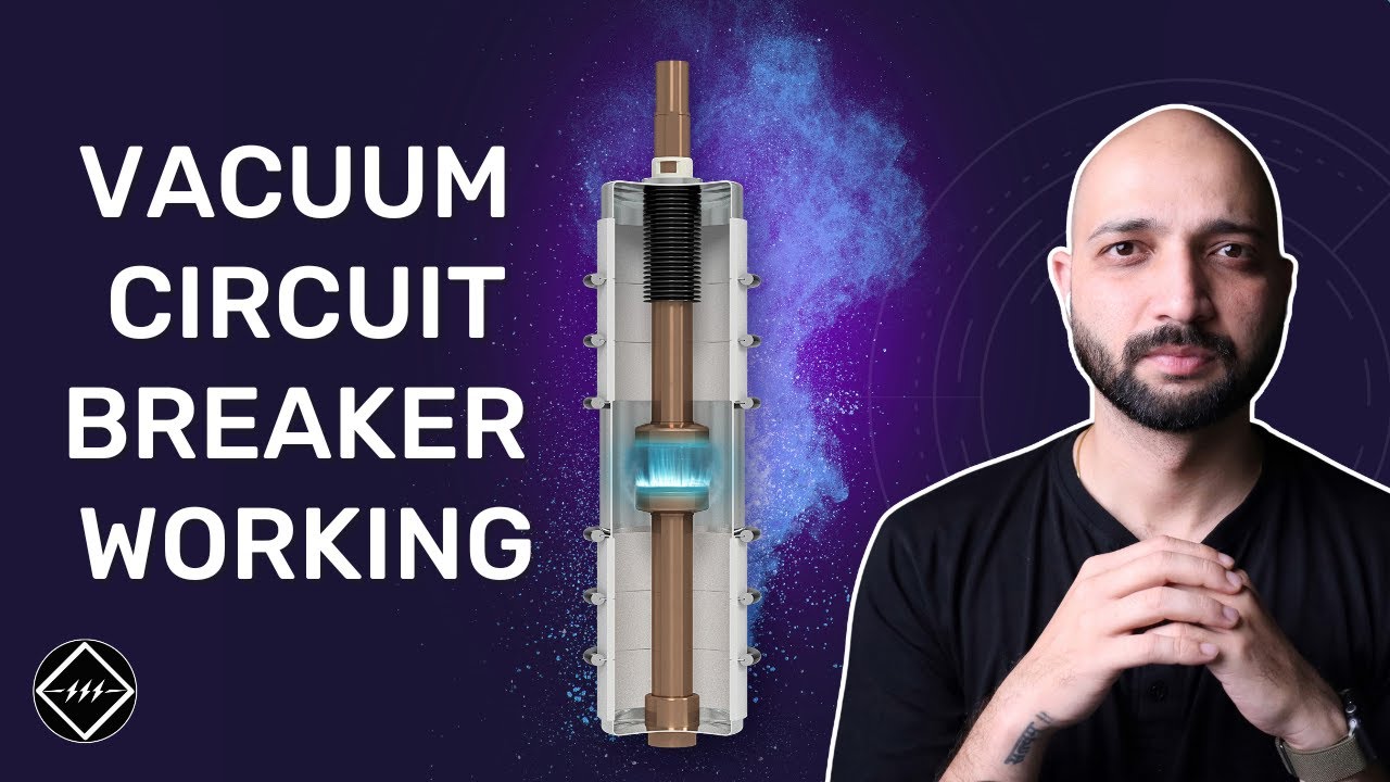
Watch Working Principle of Vacuum Circuit Breaker | Step by Step Explained | TheElectricalGuy