Dry-type transformer temperature monitoring should connect defined measurement points to documented alarm actions, cooling controls and operating records. A temperature display alone cannot show the condition of every winding location, prove the transformer is overloaded or establish that protection will operate correctly. For a new project, specify the sensor arrangement, controller functions, auxiliary supply and external interfaces together. For existing equipment, first identify what the installed channels actually measure. This guide covers the monitoring chain and its verification; insulation-class selection and transformer capacity calculations are separate engineering decisions.
Begin with the operational question
Decide what information the operating team needs and what action each indication should support. Examples include detecting an abnormal trend, calling attention to loss of cooling, issuing an alarm to a control room or initiating a documented protective response. These are different functions. State which are required before comparing controllers, otherwise a long feature list can conceal an important missing interface.
Create a simple cause-and-effect schedule. For each input condition, identify the indication, output, recipient and required response. Include abnormal measurement conditions as well as high temperature. A disconnected sensor should not quietly appear as a credible cool winding. The schedule needs review by the transformer supplier and the party responsible for protection and operations; it is not something a purchasing clerk should infer from a controller brochure.
Identify the complete measurement chain
A channel consists of more than a probe. It includes the sensor location, sensing principle, connecting leads, controller input, configuration, displayed engineering units and any onward transmission. Ask the supplier for a channel list that links these elements to the equipment drawing. Avoid accepting an unlabeled set of readings without knowing their physical meaning and any limitations attached to the measurement.
Distinguish an embedded winding sensor from a surface measurement, an ambient sensor and a temperature calculated from another input. Each can be useful, but they do not necessarily represent the same quantity. A monitoring specification should describe what each channel supports and what it cannot establish. Do not claim that a surface reading proves the maximum internal temperature or that three available channels automatically resolve every relevant hot spot.

Compare sensing options through the application
Technical context: Virtual Labs: temperature sensor measurement experiments. The checklist below is an original qualitative planning tool, not a reproduced standard.
| Artikel | Specification question | Evidence needed |
|---|---|---|
| Sensor and input | Are the sensing principle and controller input compatible? | Approved sensor and controller documentation |
| Measurement location | What part of the transformer does each channel represent? | Channel list tied to the equipment drawing |
| Cooling output | Which approved cooling functions are controlled? | Reviewed cause-and-effect schedule |
| Alarm and trip outputs | Where does each output go and what action is intended? | Interface drawings and protection review |
| Loss of signal or supply | How is an invalid or unavailable measurement announced? | Documented failure response and test record |
| Remote monitoring | Are values, units and quality status transferred correctly? | Point list and end-to-end verification record |
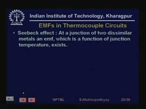
The table is an original interface checklist, not a list of mandatory setpoints. For example, resistance-based temperature measurement requires compatible interpretation of the sensor characteristic; the NPTEL temperature-measurement lecture and Virtual Labs sensor resources provide background on measurement principles. They do not select a transformer sensor or approve a particular wiring method. The supplier’s design and project requirements must establish the actual equipment arrangement.
Specify alarms without inventing universal setpoints
Do not copy alarm and trip temperatures from a different transformer simply because its insulation class appears similar. Obtain the manufacturer’s proposed settings and the engineering basis that connects them to the supplied design, operating conditions and protection strategy. Keep winding insulation class, permitted temperature rise and an alarm threshold distinct in the technical review. Their names and numbers are not interchangeable.
Record the approved setting value, units, source, revision and person responsible for changes. Include any relevant delay, hysteresis, reset behavior and latching arrangement rather than documenting only a single temperature. Where settings remain undecided, retain a commissioning hold point. A controller shipped with default values is not evidence that those values have been accepted for the project or coordinated with the rest of the installation.
Review cooling control as a separate function
If the offered transformer includes approved forced cooling, identify how the monitoring system interacts with it. The drawings should show the intended control boundary and the status information available to operators. A demand signal and proof that a fan is actually operating are different observations. Specify which information is needed and how a discrepancy is handled without assuming a controller can diagnose every mechanical or electrical failure.
Do not add fans or alter control logic solely to silence a temperature alarm. Check the offered cooling designation, auxiliary supply requirements and manufacturer instructions first. Any change in available capacity or operating duty requires supporting equipment evidence. The monitoring system can supply useful observations, but it does not create a new transformer rating by displaying a lower temperature after a local modification.
Make supply failure and sensor faults visible
Discuss what happens when the controller loses power, a sensor circuit becomes invalid or communications stop. Operators need to distinguish a valid reading from stale or unavailable information. Ask which conditions are detected locally, which reach the control room and which require another device to provide supervision. A green display during a demonstration does not answer these failure questions.
Document the intended response for each failure mode in the cause-and-effect schedule. Avoid assuming that every relay contact is fail-safe without examining its normal state and the complete receiving circuit. The appropriate response depends on the installation and its protection design. Testing should verify the agreed behavior through an approved procedure, with attention to preventing unintended operation of connected equipment during simulations.
Define remote values and event records precisely
For a supervisory interface, issue a controlled point list. Identify channel names, units, scaling, valid ranges where applicable, quality information, status indications and alarm meanings. Confirm which party supplies communication settings and how configuration changes are controlled. A communications connection that exchanges data does not necessarily prove that the receiving display presents the correct value or identifies a failed measurement correctly.
Keep event times and operating context with temperature trends. Load, room conditions, cooling state and maintenance events help explain why a value changed. A single unexplained screenshot is weak evidence for diagnosis. Establish the retention period and review responsibility based on the site’s needs. Trend analysis should flag questions for assessment, not produce an unsupported claim that a particular defect exists inside the winding.
Plan factory and site verification boundaries
Before testing, agree what the factory demonstrates and what remains to be checked after installation. The factory record can establish controller configuration and output behavior within its test arrangement. The site record should address interfaces completed by others, including the receiving indication and intended alarm destination. Allocate responsibility so neither party assumes the other has checked the full path.
Use the manufacturer’s procedure and competent personnel for any electrical testing. A useful record identifies the channel, simulated or measured condition, expected response, actual response, setting revision and limitations of the test. Simulation verifies selected parts of the chain; it may not reproduce the installed sensor’s thermal behavior. State those boundaries instead of marking the entire monitoring system proven from one injected input.
Respond to an abnormal trend with context
When a reading changes, first preserve the record and establish whether the indication is valid. Compare relevant channels, load history, room conditions and cooling status within the approved operating process. Do not open equipment to investigate merely because the controller displays a fault. Monitoring is an observation tool; safe access and diagnostic work need their own authorization, isolation and competent assessment.
Escalate unexplained or persistent changes using the site’s operating instructions and manufacturer support. Document the evidence sent for review rather than reducing the event to a message that the transformer is hot. Include the equipment identity, time sequence, channel names, settings and recent changes. Do not reset or replace a component and erase the only useful evidence of an intermittent problem before the responsible team has assessed it.
Prepare the monitoring handover package
Collect the as-built channel map, controller documentation, approved settings, interface drawings, test records and operating response instructions. Include configuration backups where the equipment supports them and identify who can authorize a change. Ensure the operating team can distinguish the sensor identity, measured quantity and intended alarm response without reconstructing the design from supplier emails.
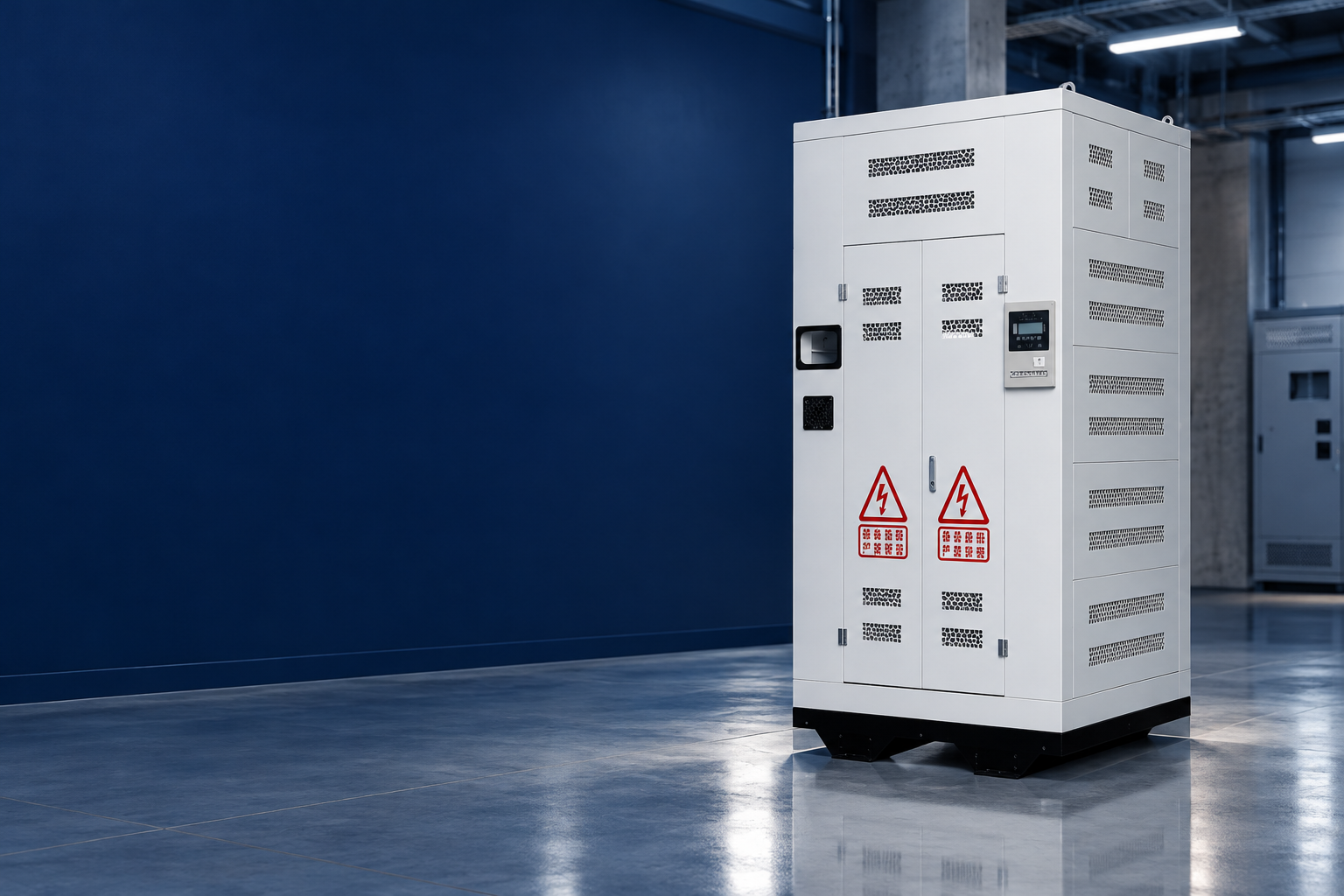
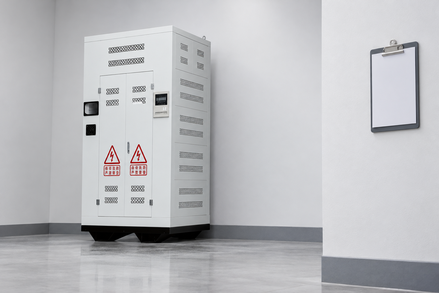
The LBAJI SCB resin-insulation transformer photograph is useful for product-family identification, but it does not establish the supplied sensor type, controller functions, communications options or exact monitoring arrangement. Include the required monitoring schedule with the enquiry and obtain a written response. Match the eventual offer to the project drawing and accepted point list rather than assuming a visible display proves every required function is included.
Häufig gestellte Fragen
What temperature should trigger a dry-type transformer alarm?
There is no universal setpoint for every design and application. Obtain the manufacturer’s proposed settings and have the responsible engineer review them against the supplied transformer, operating conditions and protection strategy.
Is a temperature display the same as transformer protection?
No. A display indicates a measured or derived quantity. Protective response also depends on settings, outputs, auxiliary supplies, connected circuits and the agreed cause-and-effect design.
Can an infrared survey replace installed temperature sensors?
They provide different observations. Establish the purpose, coverage and limitations of each method; neither should be described as proving all internal temperatures without an appropriate technical basis.
What should a commissioning record contain?
Identify the equipment and channel, configuration revision, test method, expected and observed responses, interface boundary, personnel and unresolved items. Clearly distinguish simulation of a signal from validation of the sensor’s thermal performance.
Related equipment and guides
- LBAJI SCB resin-insulation dry transformer
- Dry Type Transformer: Types, Ratings, Design & Selection
- Trockentransformator-Inneninstallation: Belüftungs- und Freiraumanforderungen
- Auswahlratgeber für Trockenisolation und Temperaturklassen
Technical references
- Virtual Labs: temperature sensor measurement experiments
- IEC 60076-11:2018: dry-type transformer scope
- HSE HSG85: Electricity at work, safe working practices
Further learning
This university lecture explains temperature-measurement principles; it does not specify transformer sensors or settings. Source: nptelhrd.