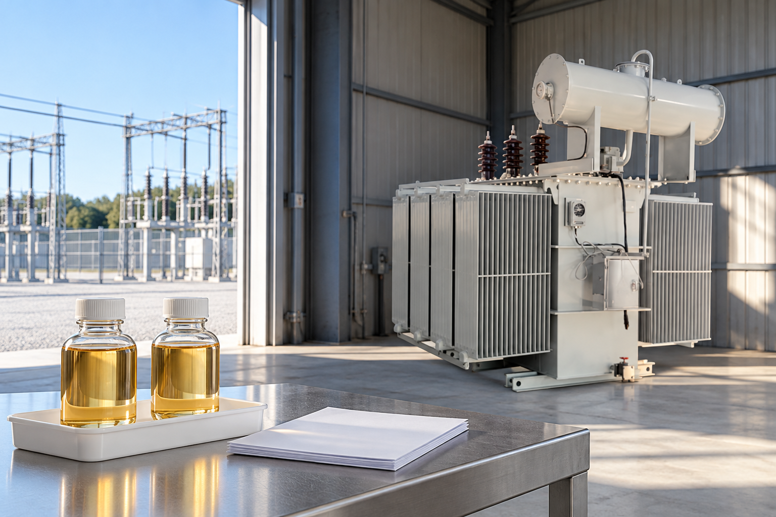
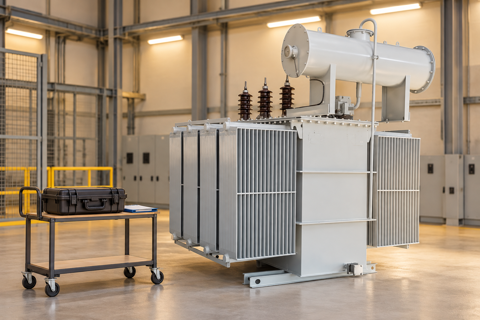
A transformer excitation current test measures the current drawn under a defined AC test arrangement to help assess the transformer’s magnetic behavior and related winding conditions. The result is meaningful only with its test voltage, frequency, connection, tap position, magnetic history and comparison basis. Different phases need not produce identical currents, and a high reading does not identify a core defect by itself. For commissioning and maintenance teams, the useful outcome is a traceable assessment of compatible results, supported by the transformer design, earlier records and complementary diagnostic evidence.
Understand the diagnostic question
Excitation current is associated with establishing magnetic flux and supplying losses under the defined test conditions. It is affected by the magnetic circuit and by how the test is applied. A field excitation-current measurement can help identify a pattern that deserves investigation, but it is not a direct measurement of insulation strength, winding resistance or available load capacity. Define the reason for the test before choosing the comparison and deciding what evidence must accompany it.
The question may be whether a new site record is consistent with a factory baseline, whether an unusual phase pattern is repeatable, or whether a suspected magnetic or winding change merits further work. These are different questions. A report that simply says current high without the underlying reference is incomplete. The responsible engineer needs to know which condition was expected, why it was expected and how the observation departs from it.
Distinguish field diagnostics from a no-load performance test
A factory no-load loss and current test and a portable field excitation-current test have related physical principles, but their conditions and reporting purposes can differ. Rated-voltage performance measurements and reduced-voltage diagnostic readings cannot be interchanged merely because both involve an unloaded winding. Supply waveform, frequency, applied voltage, tested winding and connection are part of the definition of each result.
NPTEL‘s no-load-test teaching material explains how a transformer equivalent circuit represents magnetizing behavior and losses. It provides a foundation for understanding the current, rather than a field acceptance procedure. A project should state which test is being ordered and which method governs it. If a purchase specification asks for no-load losses, a separate field current reading does not automatically satisfy that requirement.
Identify the asset and the circuit
Begin the report with the transformer serial number, approved connection diagram, winding designations, rated frequency and the exact tap position. Include the terminals used by the instrument and the condition of other relevant windings as required by the approved method. A description such as primary side is insufficient when drawings, terminal markings and instrument software use different naming conventions.
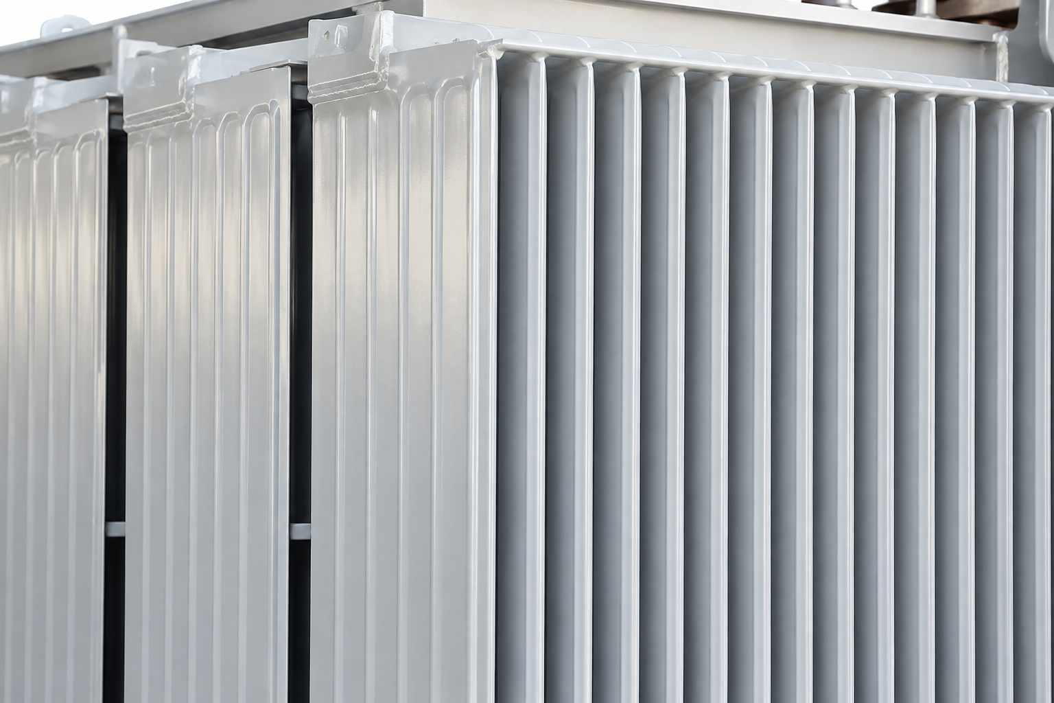
For the LBAJI 35kV oil-immersed transformer family, the product image illustrates the external equipment only. It does not establish the internal core configuration, vector group, magnetic characteristics, test current or acceptable phase pattern of an ordered unit. Request the project-specific drawings and factory records. The external presence of three bushings or a conservator cannot provide the missing electrical design information.
Voltage and frequency belong beside every reading
Magnetic flux depends on the applied voltage and frequency as well as the winding turns. Consequently, an excitation-current value cannot be compared safely with a historical number if the test conditions are unknown. A changed test voltage can produce a changed current even when the transformer itself has not changed. Near a nonlinear part of the magnetic characteristic, a simple proportional rescaling may be misleading.
Ask for the actual applied voltage and frequency, not just the instrument’s intended setting. Where the instrument stores additional information about supply or measurement quality, retain it with the result. The governing procedure and instrument manual determine suitable settings for the transformer. This guide does not recommend a universal voltage, frequency or connection scheme for all ratings and winding arrangements.
Why unequal phase currents may be expected
The magnetic paths in a three-phase transformer can differ by design. Test connection and accessible terminals can also affect the measured pattern. Therefore, three equal current values are not an automatic definition of a healthy transformer, and three unequal values are not automatically evidence of a fault. Interpretation should use the expected design behavior and compatible previous measurements.
A reviewer should ask the manufacturer or responsible specialist which pattern is meaningful for the actual transformer and method. If an old report names phases differently, reconcile the terminal mapping before deciding that the pattern has reversed. Phase order, connection configuration and tap position must travel with the values. A graph without those identifiers can make a harmless labeling difference look like a change in the equipment.
Account for residual magnetism and earlier DC tests
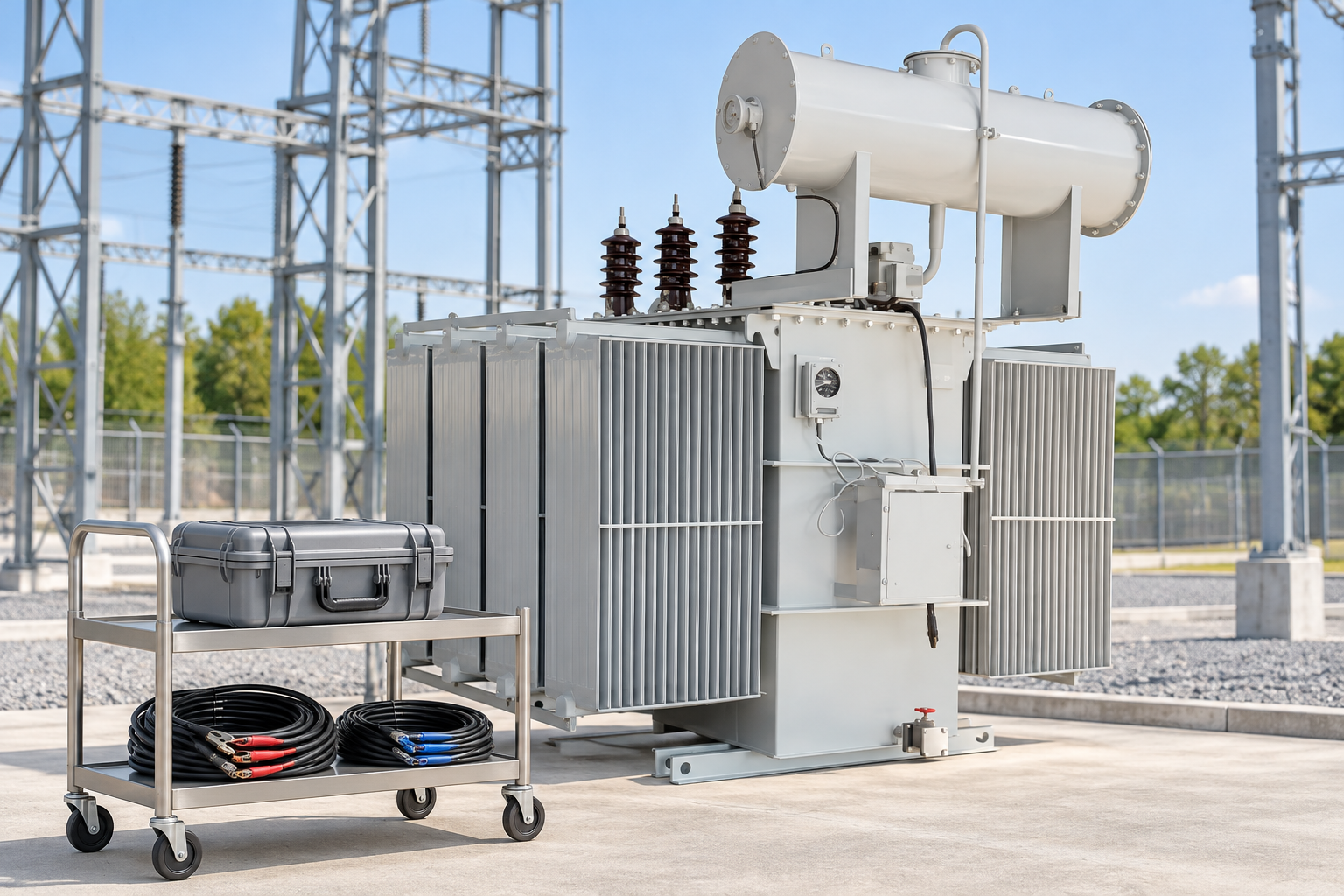
A preceding DC test can leave residual magnetism in the core and influence subsequent magnetically sensitive measurements. Winding resistance work is therefore relevant to the interpretation of a later excitation-current result. Record the test sequence and any conditioning or demagnetization performed under the approved procedure. Without that history, an unexplained difference may be assigned to the transformer when the comparison conditions are actually different.
Das Bureau of Reclamation‘s 2005 diagnostic manual specifically discusses this interaction. Its practical lesson for report review is to establish magnetic history before interpreting a change. The current instrument instructions and equipment-specific procedure govern how the team manages it. Waiting an arbitrary amount of time should not be assumed to remove residual magnetism or establish comparable conditions.
Create a comparison record that can be reproduced
The best baseline is one whose asset identity, terminals, tap, voltage, frequency and magnetic preparation are known. A factory record can be useful if the field method is compatible or an authorized engineer explains the relationship. A sister unit can provide supporting context only after its design and test conditions have been verified. Similar kVA ratings and external appearance are not sufficient evidence of an equivalent magnetic circuit.
Keep the individual phase readings and any instrument-reported loss values with their units and method. Preserve the raw observations before converting units or preparing a trend chart. If a report uses milliamperes while an older one uses amperes, normalize units explicitly. A numerical comparison should follow those checks, rather than being the first step in the review.
Excitation-current report review table
The following qualitative checklist identifies evidence needed to interpret the test. It does not provide acceptance limits, authorize a test arrangement or prescribe energization steps.
| Evidence area | Record to retain | Interpretation risk when missing |
|---|---|---|
| Asset identity | Serial number and drawing revision | Comparison may belong to another design |
| Connection | Winding, terminals, phase labels and tap | A connection difference can change the pattern |
| Applied supply | Actual AC voltage and frequency | Different magnetic stress can alter the reading |
| Magnetic history | Earlier DC tests and approved conditioning | Residual magnetism can affect comparison |
| Baseline | Compatible factory or previous field record | A standalone number has limited diagnostic value |
| Entscheidung | Specialist assessment and follow-up | A repeatable anomaly still needs explanation |

Use trends without creating a universal threshold
A percentage change can summarize a compatible comparison: change (%) = 100 × (new current − baseline current) / baseline current. Both currents must use the same units and refer to the same circuit and conditions. The baseline must be nonzero. When the reference is very small, a percentage can exaggerate a modest absolute difference, so retain the underlying values and instrument capability as well.
For an arithmetic example, a baseline of 10.0 mA and a new reading of 11.0 mA give a +10% change. These hypothetical values illustrate reporting only; neither current nor percentage is an acceptance limit for a transformer. If voltage, frequency or magnetic preparation differed, the calculation may describe incompatible tests. A well-presented percentage does not repair that underlying evidence problem.
Investigate an unexpected result before assigning a cause
Start with the record itself. Check units, terminal labels, tap position, configured connection, applied voltage and frequency. Establish whether DC testing occurred before either measurement and whether the preparation was comparable. Review instrument status and any interruptions noted by the operator. These checks help separate a documentation or setup problem from a repeatable equipment-related observation.
If an unexplained difference remains, the competent test team should agree a controlled repeat and preserve both sets of readings. The manufacturer or responsible diagnostic engineer can then select complementary evidence, which may include ratio measurements, winding resistance, loss information, oil diagnostics or other appropriate tests. Do not declare a shorted turn or damaged core solely from one unexplained current value; the conclusion needs a supported diagnostic argument.
Coordinate safe testing and restoration
The test introduces AC voltage into a transformer and can create hazards beyond the instrument terminals. Isolation, adjacent equipment, induced voltages, access control and the condition of other windings must be addressed by a competent team using the approved method. HSE HSG85 provides a general framework for electrical safe working practices. It does not replace the equipment-specific risk assessment, permits or switching instructions.
The service scope should identify who controls isolation, who operates the test equipment and who verifies restoration after testing. Any removed connections, temporary arrangements and final tap settings require appropriate checks and records. A teaching video is useful for understanding the equivalent circuit, but it is not permission to repeat a laboratory connection on installed high-voltage equipment.
Specify useful evidence in the inquiry
When ordering testing or a new transformer, describe the diagnostic or acceptance question and request a report format that retains the relevant conditions. Include the actual rated voltages, frequency, vector group and tap schedule when known. Ask whether a factory baseline is available and whether it is intended for comparison with the proposed site method. Agree which differences require manufacturer review before shipment or energization.
A good handover package separates measurements from interpretation. It identifies the governing documents, responsible reviewer, unresolved questions and next actions. Where an exception has been resolved through corrected labels or a controlled repeat, retain the original record and explanation. That history allows the next maintenance team to distinguish an established characteristic from a new observation instead of starting the investigation again.
Häufig gestellte Fragen
Must the three phase currents be equal?
No. The expected pattern depends on the transformer design and test connection. Use compatible baselines and manufacturer guidance rather than assuming equality.
Can an earlier winding resistance test affect the result?
Yes. DC testing can leave residual magnetism that affects magnetic measurements. Record the sequence and follow the approved conditioning procedure.
Is a field excitation current reading the same as factory no-load loss?
No. The methods, applied conditions and reported quantities can differ. State the required test and comparison basis explicitly.
Does a high current prove a core fault?
No. Verify the conditions, records and repeatability, then assess complementary evidence with the responsible specialist before diagnosing a cause.
Related equipment and guides
- LBAJI 35kV oil-immersed power transformer
- Komplettleitfaden zu den Grundlagen von Transformer-Modellen
- Transformer Testing: Methods, Procedures & Test Checklist
- Werksabnahmeprüfung für Leistungstransformatoren: Checkliste für die Teilnahme des Importeurs
Technical references
- Bureau of Reclamation: Transformers, Basics, Maintenance and Diagnostics (2005; historical background)
- IIT Madras NPTEL Electrical Machines I: Testing of Transformers
- HSE HSG85: Electricity at work, safe working practices
Further learning: No-load test and magnetizing behavior
This IIT Kharagpur NPTEL lecture explains the no-load test and equivalent-circuit parameters. It supports the distinction between magnetizing behavior and losses. It is a laboratory-theory lesson, not a field excitation-current procedure or an acceptance limit. Source: NPTEL IIT Kharagpur.

Watch Lecture 16: Determination of Equivalent Circuit Parameters – No Load Test