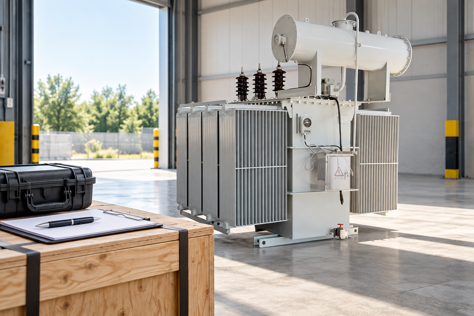
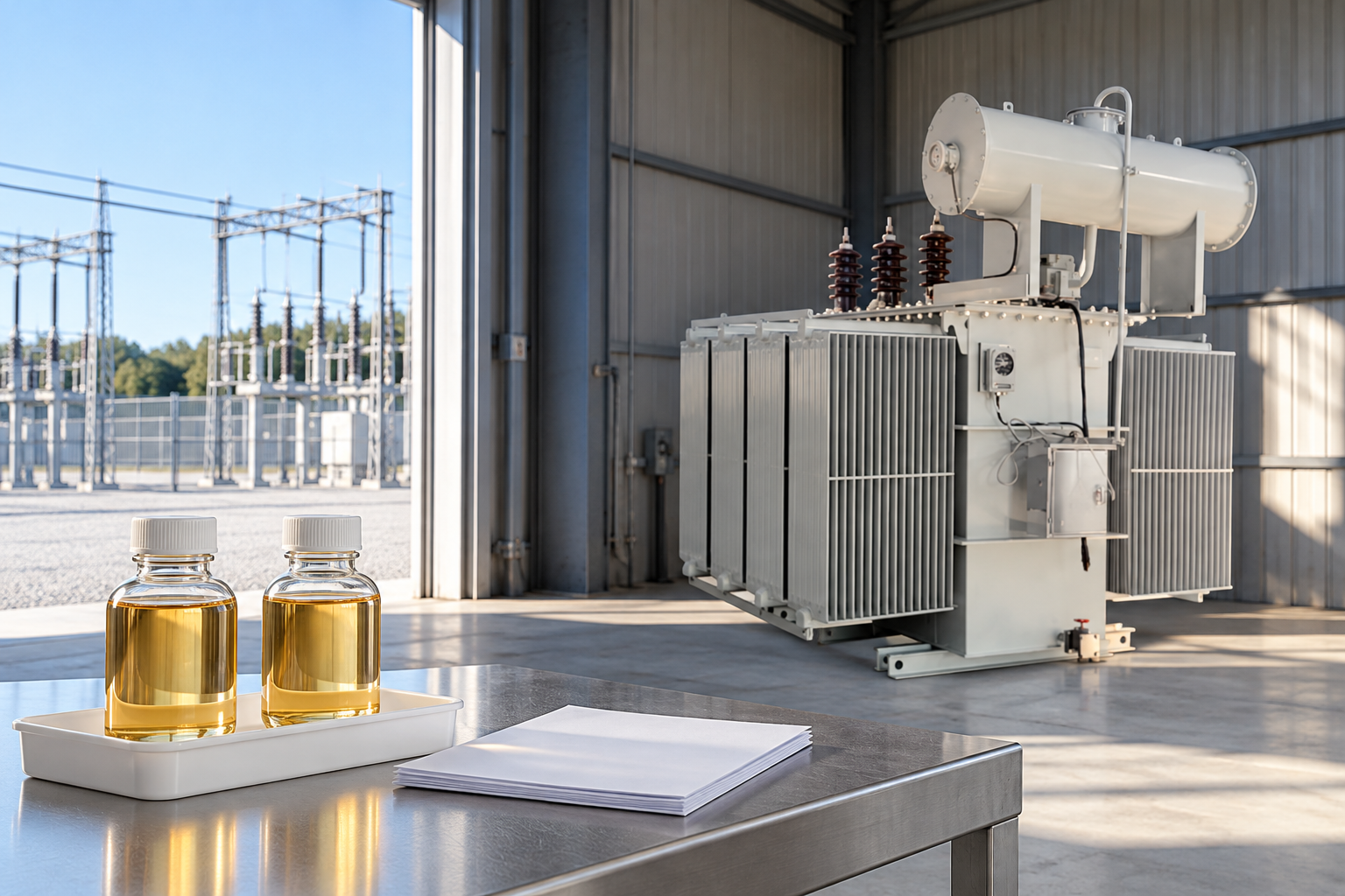
A transformer core ground test investigates whether the magnetic core has an unintended connection to the grounded structure, using a procedure appropriate to the actual transformer design. The review must distinguish the intended core earth connection from a second, unwanted path. It is not the same as measuring a substation earth electrode or checking the protective earth of the tank. A useful report identifies the test boundary, documents the condition of the intended connection during measurement and confirms its correct restoration before service. A resistance number without those records can be misleading.
Why the intended core connection matters
The magnetic core and its supporting arrangement are part of an engineered insulation and grounding design. The intended connection controls the core’s electrical reference. An additional path can create conditions for circulating current and localized heating. However, the actual construction and accessibility of the connection vary. A general explanation of single-point grounding is not a wiring drawing for every transformer.
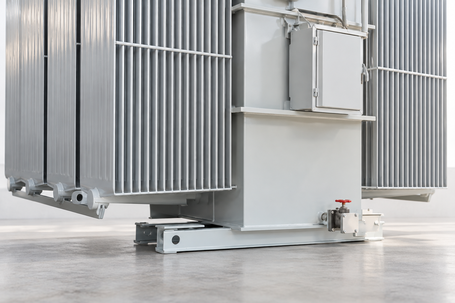
Start with the manufacturer’s documentation for the specific serial number. Identify the core, clamps, frame and tank connections as applicable. Do not assume that every accessible earth lead serves the same function or that every assembly is meant to be separated for testing. A photograph of the outside of an oil-filled transformer cannot establish its internal core-ground arrangement.
Core insulation testing and tank earthing answer different questions
Tank protective earthing provides an essential safety function. A core insulation investigation examines a different circuit boundary. Removing a tank earth to make a core test appear satisfactory would confuse those functions and can introduce a serious hazard. All changes to connections must follow the equipment-specific procedure and the site’s controlled electrical work system.
Similarly, an earth-grid resistance result does not demonstrate that the magnetic core has no unintended internal ground. A winding-to-earth insulation measurement is also a different measurement. The report should name exactly what was measured and avoid the ambiguous statement that the transformer grounding test passed when only one of these functions was examined.
When an investigation may be appropriate
An investigation may follow suspicious diagnostic evidence, repair work, a significant event or a specified maintenance requirement. The trigger should be recorded. If oil analysis indicates heating, the engineer must consider alternative causes rather than assigning the gases exclusively to a core-ground problem. Poor electrical connections and other defects can also require investigation.
Das Bureau of Reclamation transformer manual discusses inadvertent core grounds within a broader diagnostic programme. It is useful historical background, rather than a source of automatic limits for every modern product. Select the investigation from the equipment history and technical documentation. Routine repetition without a clear test boundary may produce numbers that cannot support a decision.
Agree the test boundary before the outage
Before work begins, the owner and test specialist should identify which connection can be accessed, which part will be tested and whether the transformer design allows the planned measurement without internal access. If relevant documentation is missing, obtain clarification from the manufacturer. Unplanned disassembly should not become the default response to an unfamiliar terminal.
The plan should also define the isolation, access, discharge and restoration responsibilities. HSE HSG85 explains principles of safe electrical work, but the site still needs its own authorized procedure and competent personnel. This article provides a framework for reviewing that work, not instructions to disconnect a core ground or apply a particular test voltage.
What a useful measurement record contains
Record the asset and serial number, drawing reference, test connection identification, instrument identification and applicable calibration status. Include the selected measurement conditions, test duration where relevant, ambient or equipment condition and the location of any temporary disconnection. Keep the original readings and describe the units clearly rather than transcribing an unexplained number into a summary.
For a trend comparison, explain whether the same part of the insulation system was measured under comparable conditions. Changes in accessibility, external paths or procedure can make an apparent trend unreliable. The reviewer needs enough information to decide whether a changed value represents the equipment, the test boundary or a documentation error.
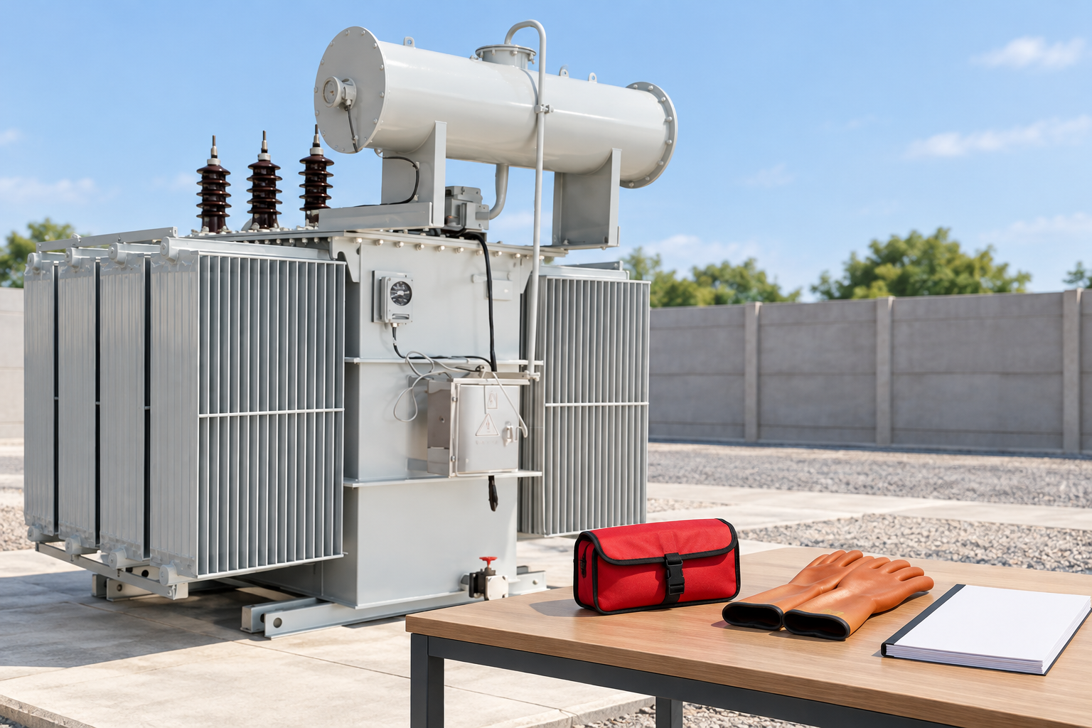
Review matrix for the handover package
This table is a qualitative document-review aid. It does not prescribe a test voltage or acceptance resistance. The agreed procedure and manufacturer’s requirements determine those decisions for the actual equipment.
| Prüfungselement | Erforderliche Beweislage | Meaning of a missing item |
|---|---|---|
| Grounding arrangement | Equipment-specific drawing identifying intended core and structure connections | The measured circuit may not be understood |
| Measurement boundary | Record of the tested points and any authorized temporary disconnection | The reading cannot establish the claimed insulation condition |
| Instrument and conditions | Instrument identity, selected test conditions and original readings | Repeatability and comparability remain uncertain |
| Unexpected result | Verification record and specialist assessment of alternative paths | A low value is not yet a located internal defect |
| Restoration | Confirmation that intended connections and covers were restored and checked | The equipment handover is incomplete |
| Release decision | Authorized disposition linked to the findings and remaining actions | A completed test sheet does not authorize energization |
Interpret an unexpected low resistance carefully
A low reading can justify investigation, but first confirm that the intended measurement boundary was achieved and that an external connection has not remained in the circuit. Check the record, equipment identity and approved procedure. A test made with the normal intended core ground still connected may not answer the insulation question the reviewer thinks it answers.
If a repeat under the verified procedure confirms an abnormal result, the responsible specialist should assess the likely location and significance. Avoid assigning an exact internal defect from one number. The investigation may require manufacturer advice and other diagnostic findings. Any intrusive work should be separately planned, including its effect on the oil system and contamination control.
Why a high reading is not the end of the job
A favourable insulation measurement only describes the tested boundary under the stated conditions. It does not confirm the integrity of every intended grounding connection, the condition of all windings or the absence of other transformer defects. It also does not establish that temporary test changes have been reversed.
This is why restoration evidence belongs in the same handover package as the reading. A high resistance obtained while the intended ground was isolated is not a reason to leave the core floating in operation. The procedure must restore the designed arrangement and verify the relevant connections before the equipment is released. The approved drawing governs that restoration.

Coordinate the diagnostic sequence
Direct-current testing can leave residual magnetism that affects subsequent excitation-current and frequency-response comparisons. The Bureau of Reclamation manual highlights this issue. Record the order of tests and any approved demagnetization activity so the engineer can interpret later results in context. An abnormal trace after a changed sequence may require a controlled repeat rather than a new fault label.
The diagnostic plan should also avoid circular reasoning. Oil analysis can motivate a core-ground investigation, but a suspected core problem should not be treated as already proven when interpreting the oil report. Keep observations, hypotheses and confirmed findings separate. This makes the final assessment easier to audit and reduces unnecessary repair work.
Example: a low result with an uncertain connection record
Imagine a maintenance report that lists low resistance but does not state whether the intended core connection was isolated as specified. The immediate issue is incomplete evidence. Ask the test team to identify the boundary from the drawing and original records. If the boundary cannot be reconstructed, the engineer can decide whether another controlled measurement is necessary.
The example is hypothetical and supplies no acceptance number. If a verified repeat remains abnormal, retain both records and document the specialist’s next action. If the apparent fault disappears after correcting a measurement arrangement, explain the correction without deleting the initial reading. That history prevents a future reviewer from interpreting the unexplained first result as a persistent defect.
Avoid improvised attempts to remove an unwanted ground
Older diagnostic literature sometimes describes specialized remedial techniques. Such descriptions are not permission to apply current, improvise a connection or attempt to remove an internal path. An uncontrolled intervention can damage insulation, generate gases or obscure the original diagnostic evidence. The equipment owner needs an engineered repair decision, not an internet shortcut.
If a confirmed unwanted connection requires correction, agree the scope with the manufacturer or an appropriately qualified specialist. Record the chosen intervention, its risks, the verification measurements and any follow-up monitoring. Preserve pre-repair evidence so later results can be compared with a known starting condition.
What to include in a transformer enquiry
For an LBAJI 35kV oil-immersed transformer enquiry, describe the required drawings, accessibility information and maintenance documentation. Ask whether any project-specific core-ground test or witness point is included, and obtain written confirmation. Do not infer an externally accessible test point, a removable link or a particular core arrangement from the catalogue image.
For an existing installation, provide the serial number, available drawings, relevant test reports and the reason for investigation. Identify whether the request concerns factory evidence, site maintenance support or a repair assessment. These details allow the proposed work to be matched to the equipment instead of quoting a generic grounding test with an uncertain scope.
Close the work with a clear condition statement
A complete conclusion states what was measured, whether the result met the agreed criteria and what limitations remain. It also records restoration and the authorized operating disposition. Keep that conclusion separate from assumptions about remaining life or the condition of unrelated components. The core-ground test is one part of an overall assessment.
Store the final report, original readings, drawings and restoration checks together in the asset record. If follow-up work is required, give it an owner and a defined objective. A traceable package supports future maintenance and helps prevent temporary test arrangements from being mistaken for the normal design.
Häufig gestellte Fragen
Is a core ground test the same as an earth-grid resistance test?
No. The core-ground investigation concerns an equipment-specific internal grounding and insulation boundary, while an earth-grid test concerns the installation earthing system.
Does low core insulation resistance prove a particular internal defect?
No. Verify the test boundary, intended connection state and alternative paths, then obtain a specialist assessment supported by appropriate additional evidence.
Can the intended core ground remain disconnected after a good reading?
No. The approved equipment procedure must restore and verify the designed grounding arrangement before service release.
Does every oil-immersed transformer have an external core test terminal?
No such feature should be assumed. Confirm the actual arrangement and accessibility from the manufacturer’s documentation for the specific transformer.
Related equipment and guides
- LBAJI 35kV oil-immersed power transformer
- Komplettleitfaden zu den Grundlagen von Transformer-Modellen
- Transformer Winding Resistance Test: Temperature, Tap Position and Report Review
- Transformer Turns Ratio Test: Nameplate, Tap Schedule and Result Review
Technical references
- Bureau of Reclamation: Transformers, Basics, Maintenance and Diagnostics (2005; historical diagnostic background)
- NPTEL IIT Kharagpur: Electrical Machines I (core loss background)
- HSE HSG85: Electricity at work, safe working practices
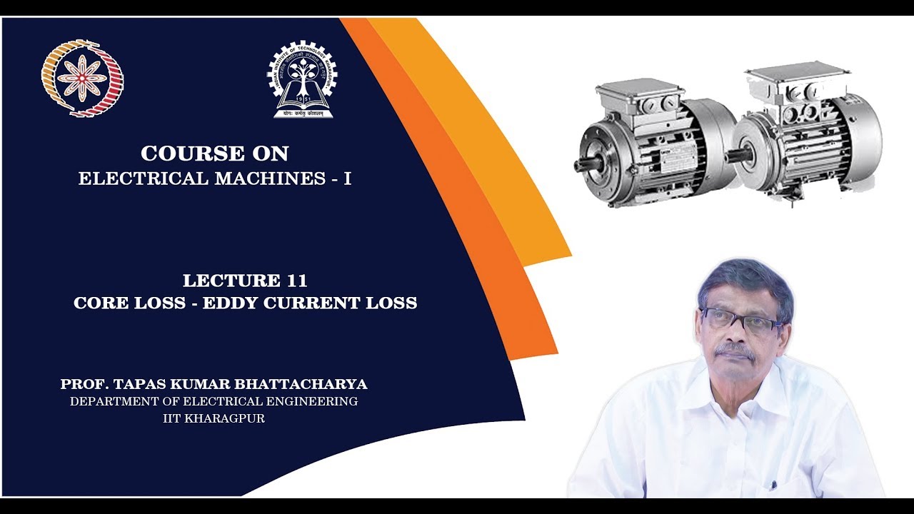
Further learning: Core loss and eddy currents
This IIT Kharagpur NPTEL lecture explains transformer core losses and eddy currents. It provides background for understanding unwanted circulating-current heating; it does not demonstrate a core-ground test, authorize disconnection or provide equipment-specific resistance limits. Source: NPTEL IIT Kharagpur.