Switchgear grounding and bonding must be coordinated across the supplied assembly, its installed interfaces and the site’s protective system. Grounding connects the relevant system or equipment to the designated earth arrangement; bonding establishes the required electrical continuity between conductive parts. The exact construction, conductors and verification criteria depend on the installation and applicable requirements. A ground symbol on a drawing or a closed metal cabinet does not prove that every interface has been completed correctly. Buyers should obtain supported equipment details, assign interface responsibilities and retain the inspection and verification records for the actual installation.
Separate the functions before reviewing the hardware
Protective grounding and bonding are different from normal circuit-current paths, signal references and the temporary arrangements used during particular work procedures. These terms can be mixed casually in a tender, creating uncertainty about what the supplier is expected to provide. Begin with the system design and identify the function of each relevant conductor and interface. Keep neutral, protective and other connections defined by the actual project requirements rather than treating every earth-related label as interchangeable.
This article is a documentation and procurement guide, not instructions for installing or testing a grounding system. It does not supply conductor sizes, resistance limits or permission to work on energized equipment. Those decisions require qualified engineering and the applicable installation rules. The official electrical references linked below describe their respective U.S. regulatory context; projects elsewhere must use their own applicable requirements and supported equipment instructions. Preserve that jurisdiction and equipment boundary when reviewing a general technical reference.
Define the supplied assembly boundary
Ask what grounding and bonding provisions are included in the factory-supplied configuration and what must be completed on site. The boundary can include the enclosure, specified conductive parts and designated interfaces to the installation. Request drawings and instructions for the actual order. Do not infer hidden connections from a photograph or assume that a generic family brochure describes every circuit and accessory fitted to the delivered equipment.
Shipping sections and site assembly can introduce interfaces that require controlled completion. Identify who supplies the necessary parts, who installs them and who records verification. A supplier statement that the assembly has grounding provisions does not mean that the completed installation has been assessed. The acceptance process should connect the factory configuration with the actual site work. This makes missing responsibilities visible before the equipment is energized rather than leaving each contractor to assume that another party completed the interface.

Review the project system information
The responsible engineer should provide the system and protective information needed to assess the offered assembly and its connection requirements. The equipment supplier needs the relevant arrangement and site conditions, not merely an instruction to add an earth bar. Confirm what information belongs in the quotation and what must be resolved before manufacturing or installation. Differences between the assumed and actual system should be raised explicitly.
Do not copy an arrangement from another project because the cabinet dimensions or supply voltage appear similar. System conditions and applicable requirements can differ. Keep any protective and neutral interfaces aligned with the approved circuit design. The owner also needs a clear explanation of what later changes would require review. Grounding and bonding records should remain part of the electrical design package rather than becoming an isolated set of marks added to an installation drawing at the end of construction.
Inspect interfaces through a controlled process
Prepare an interface register covering the relevant equipment and contractor boundaries. Identify each required connection by its function and drawing reference. Inspection must use authorized access and safe work procedures. This guide does not direct a reader to remove panels, touch conductive parts or perform measurements on an operating assembly. Qualified personnel should determine what access and verification are appropriate for the actual equipment and state.
Record the condition and identity of the interface, not simply a tick saying earth complete. The technical record should make it possible to identify what was inspected and against which approved detail. Where an interface is inaccessible at final acceptance, its earlier completion evidence can be important. Agree these records before installation. A missing inspection record should not be filled retrospectively from memory or replaced by a photograph that cannot establish the relevant connection.
Use a responsibility and evidence table
The following qualitative table organizes the coordination work. It is an original checklist rather than a reproduced wiring method or a source of universal acceptance values.
Referenzkontext: 29 CFR 1910.304 grounding and protection, official2025 edition. Diese ursprüngliche qualitative Checkliste organisiert die Projektentscheidungen; sie ist keine reproduzierten Standardformel oder ein Ersatz für genehmigte Kriterien.
| Interface area | Information to request | Evidence to retain |
|---|---|---|
| Factory assembly | Included provisions and actual configuration | Supplier drawings and supported instructions |
| Shipping-section joins | Required site-completed interfaces and parts | Installation and inspection record |
| External protective connection | Approved system detail and contractor responsibility | Completed interface verification |
| Doors and removable parts | Supported provisions and maintenance conditions | Inspection and replacement records |
| Cable and enclosure interfaces | Approved entry and conductive-part arrangements | Site completion evidence and deviations |
| Later modifications | Review and re-verification requirements | Revised drawings and technical disposition |

Treat doors and removable components carefully
The design may establish particular bonding provisions for doors, covers or removable parts. Ask the manufacturer what is required and how it is maintained. Do not assume that a hinge, painted joint or physical contact supplies the intended continuity without supported design information. Likewise, do not invent a universal bonding strap arrangement for an unknown cabinet. The actual construction and applicable requirements determine the necessary provisions.
Maintenance can change these interfaces. A replaced door, altered cover or removed component should be assessed under the supported instructions. Record the replacement identity and relevant verification rather than relying on visual similarity. The owner should know which features must be restored after access and what constitutes an unresolved defect. This is a practical reason to retain the manufacturer’s drawings: future personnel should not have to reconstruct the intended connections from the cabinet’s current appearance.
Coordinate cable entries and connected metalwork
Cable and enclosure interfaces require the actual project information and approved installation details. The electrical designer and supplier should identify which conductive parts and connection arrangements belong to the protective system and how completion is verified. Do not leave a contractor to resolve these relationships by drilling a convenient opening or substituting an unfamiliar entry component. Such changes may also affect enclosure protection and the assembly’s supported construction.
Include interface responsibility in the RFQ and installation scope. A complete equipment package can still arrive without the parts or information needed for a particular site connection if the boundary was never stated. Keep approved deviations and replacement decisions with the final drawings. The owner needs to understand the completed arrangement, including interfaces to associated equipment, rather than receive separate supplier and contractor statements that cannot be reconciled into one installation record.
Choose verification criteria from the right documents
Verification should follow an approved plan for the actual installation, with methods and criteria established by the responsible technical parties. The plan should state the boundary, equipment condition, instruments and records required. Do not apply a familiar numerical threshold without confirming what it represents and whether it is appropriate. A single test result does not automatically demonstrate every grounding and bonding function in a complex installation.
Preserve the distinction between inspection, measurement and complete protective-system assessment. Each can provide useful evidence, but they do not answer identical questions. If a result is outside the accepted criterion, obtain a supported technical disposition and retain the corrective and re-verification records. Avoid repeating a measurement until a favourable number appears without explaining the earlier observation. The final record should establish what was accepted and why, not merely present the last result obtained.

Keep work procedures separate from equipment features
Grounding and bonding provisions do not eliminate the need to control energy sources and verify the required condition before electrical work. A closed switch, an earth symbol or an external indicator is not a complete work authorization. Qualified personnel must use the procedures for the actual installation and the task. The official work-practice reference below helps distinguish these responsibilities from the construction features supplied with the equipment.
Temporary work-related arrangements, where required, must also be governed by the applicable procedures rather than confused with the permanent protective system. This article deliberately gives no switching or connection sequence. If equipment condition or documentation is uncertain, the responsible authority should assess it before work proceeds. Procurement and handover records can support that assessment by making the intended interfaces and restrictions clear, but a general article cannot establish a safe condition for a specific installed cabinet.
Maintain traceability after handover
The final package should connect equipment identity, approved drawings, interface records, verification results and accepted deviations. Keep it searchable by assembly and circuit. Maintenance personnel should be able to find the relevant instructions without relying on a supplier’s generic product page. Include the process for reviewing changes, so that later cable additions or component replacements do not silently alter an interface on which the original design depends.
Record defects and their closure with enough detail for a future reviewer to understand the decision. Where original documentation is incomplete, seek a supported assessment rather than guessing the arrangement from a similar cabinet. An old label or ground symbol remains physically present after modifications, but its presence does not approve the changed installation. The owner needs a maintained record describing the actual equipment, not a collection of historical documents whose applicability is no longer clear.
Apply the review to a real procurement request
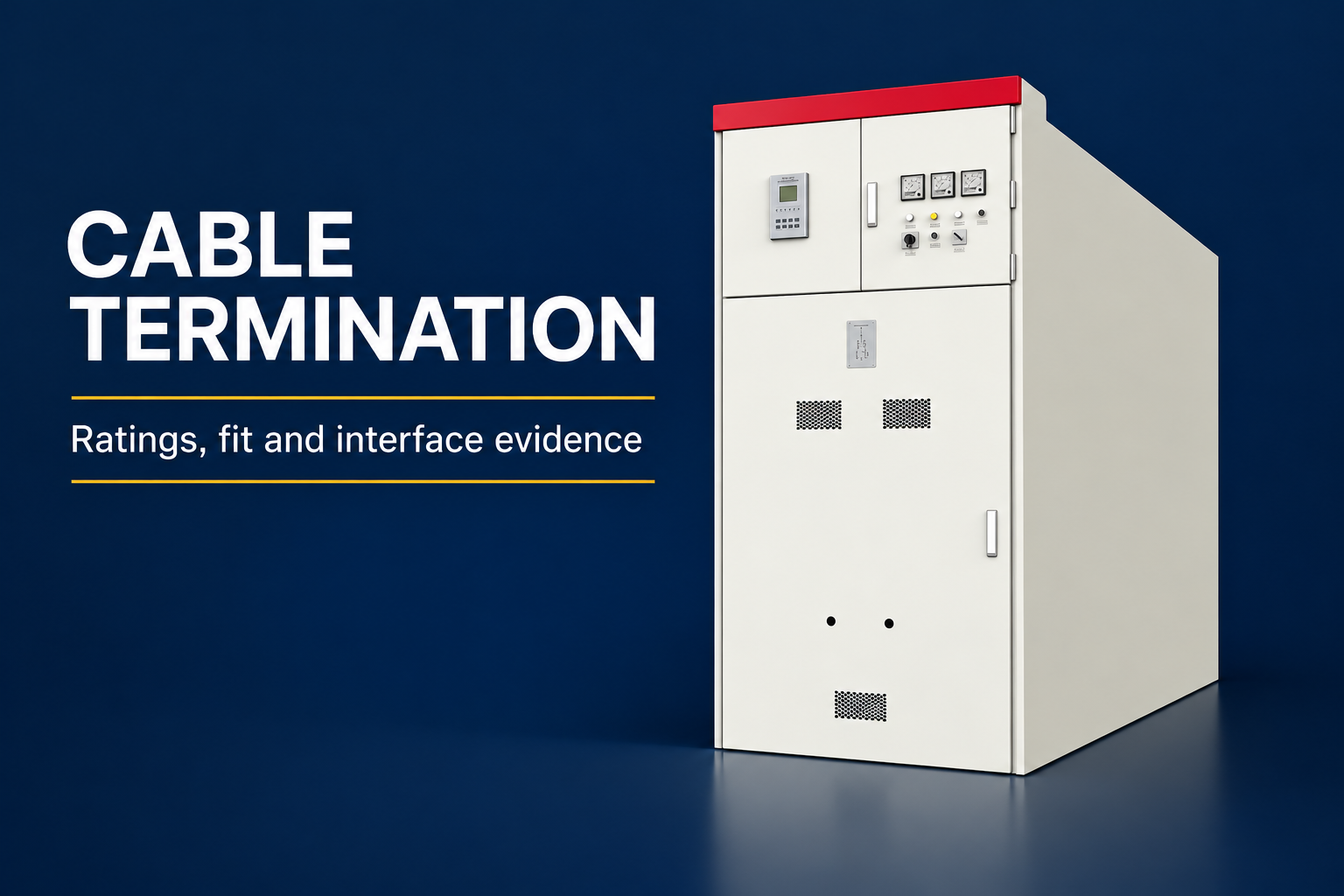
The GGD reference images show a real LBAJI low-voltage cabinet exterior. They preserve visible panels and controls without inventing green conductors, earth terminals or an internal connection diagram. The ordered assembly’s protective interfaces must be established from its actual design and installation documents. Request those details together with the circuit information and site requirements needed by the supplier and engineer.
A useful RFQ names the included provisions, external interfaces, responsible parties and evidence required for acceptance. Compare offers on the same boundary instead of assuming that grounding included means identical scope. The practical result is a coordinated installation record linking the supplied assembly to the site’s protective system, followed by maintenance arrangements that preserve the approved interfaces. That record is more valuable than an unsupported promise based on cabinet appearance or an isolated numerical result.
Häufig gestellte Fragen
Does a metal cabinet prove that bonding is complete?
No. The actual design, interfaces and completion evidence must establish the required continuity. Exterior appearance is insufficient.
Can a hinge be assumed to provide the required bonding?
Not without the supported design and applicable requirements. Ask the manufacturer what provisions must be maintained for the actual door or removable part.
Is one resistance result a complete protective-system assessment?
Not automatically. Confirm the purpose, boundary and criteria of each inspection or measurement under the approved verification plan.
Can a grounding diagram from another project be reused?
Only through an appropriate assessment of the actual system, equipment and requirements. Similar appearance or nominal voltage does not establish equivalence.
What should be handed over to the owner?
Provide equipment identities, approved interface drawings, installation and verification records, accepted deviations, maintenance instructions and the process for reviewing later changes.
Technische Quellen und damit verbundene Ausrüstung
Standardkatalogseiten legen den Dokumentenbereich fest; die Einhaltung und Annahme erfordern die vollständigen Dokumente und eine Projektüberprüfung.
- 29 CFR 1910.304 grounding and protection, official2025 edition
- 29 CFR 1910.333 – Praktiken für elektrische Arbeiten – offizielle Ausgabe 2025
- IEC 61439-2 power switchgear and controlgear assembly scope
- LBAJI GGD Niederspannungs-Schaltanlagen
- Grundlagen der Schaltanlagen-Ausrüstung
- Überprüfung und Prüfung der Schaltanlagen
- Checkliste für die Wartung von Schaltanlagen
Weiterführender Lernstoff: Gerätefunktionen
Diese unabhängige Bildungsunterlage erläutert die technischen Grundlagen der Geräte. Sie vermittelt jedoch keine sichere Arbeitsmethode für die jeweilige Montage. Quelle: Gaurav J – TheElectricalGuy.

Watch Switchgear Basics: Komplettanleitung für Einsteiger | TheElectricalGuy