Switchgear testing is the planned verification that an installed assembly and its protection system perform the functions required by a particular electrical design. It is not one universal “megger test,” nor is it the same as a general maintenance walk-through. A useful test program identifies the asset, the question each test answers, the safe electrical state, the manufacturer-approved method, the acceptance criteria and the recorded result. The work belongs to qualified personnel using an approved site procedure. This guide explains what to specify and how to interpret a test program; it does not give live-work instructions or universal pass values.
Which testing phase are you planning?
Factory routine tests verify an assembled product against its production requirements before shipment. Site acceptance tests verify that delivered equipment, connections, protection and installation are suitable for initial energization. Commissioning adds functional checks across the complete scheme—breaker, relay, controls, alarms and network interfaces. Later diagnostic testing investigates a defect or establishes trends during service. These phases overlap in methods but differ in purpose and evidence. Repeating a factory test in the field without understanding its assumptions may be unnecessary or harmful.
El InterNational Electrical Testing Association’s acceptance-testing scope describes field checks for suitability before initial energization. The applicable edition, contract, equipment manuals and governing jurisdiction determine the actual tests and criteria. A project should not simply paste a broad checklist into a purchase order and assume every item applies to every cabinet.
Build a test matrix around failure modes
Start with the single-line diagram, equipment schedule, protection study, approved settings and manufacturer data. Separate the assembly from its components: enclosure and bus, circuit breaker or switch, current and voltage transformers, protective relay, control power, auxiliary wiring and cable terminations. Then ask what failure each proposed test could find. A continuity check may reveal a broken path but not insulation integrity; an insulation measurement can reveal some contamination or damage but not a wrong protection setting. A successful relay injection does not prove the trip coil is wired correctly unless the end-to-end scheme is also verified.
| Test or check family | Question it can address | Important limit |
|---|---|---|
| Visual and mechanical verification | Correct assembly, damage, labels, interlocks and operating condition | Cannot establish hidden dielectric or relay performance |
| Insulation assessment | Gross insulation problems under a specified setup | Result depends on connected electronics, temperature, humidity and test method |
| Contact or main-circuit resistance | Abnormal high-resistance joints or contacts | Needs comparable setup, instrument and manufacturer limits |
| Breaker timing and travel | Operating sequence, pole agreement and mechanism behavior | Applies to the specific breaker and approved access method |
| Protection injection and logic | Relay pickup, timing, inputs, outputs and scheme response | A relay-only test may miss CT polarity or final trip-path errors |
| Functional end-to-end test | Actual alarms, trips, interlocks and indications | Requires controlled plan so test signals do not cause unintended outages |
IEC 62271-200:2021 addresses AC metal-enclosed switchgear above 1 kV up to 52 kV, including assembly requirements. It does not supply a single field-test recipe for every relay, cable and connected load. Record the standard edition and the model-specific acceptance document actually used.
Make safety prerequisites explicit
Testing can introduce energy from test sets even when the normal supply has been isolated. A plan must identify all supply and backfeed paths, stored energy, neighboring energized compartments and the exact points where test voltage or current will be applied. Qualified workers establish isolation, lockout, absence-of-voltage verification and grounding or earthing as required by the approved procedure. Temporary leads and links need an installation-and-removal record. An energized functional test requires a different risk assessment and authorized operating sequence from an offline insulation test.
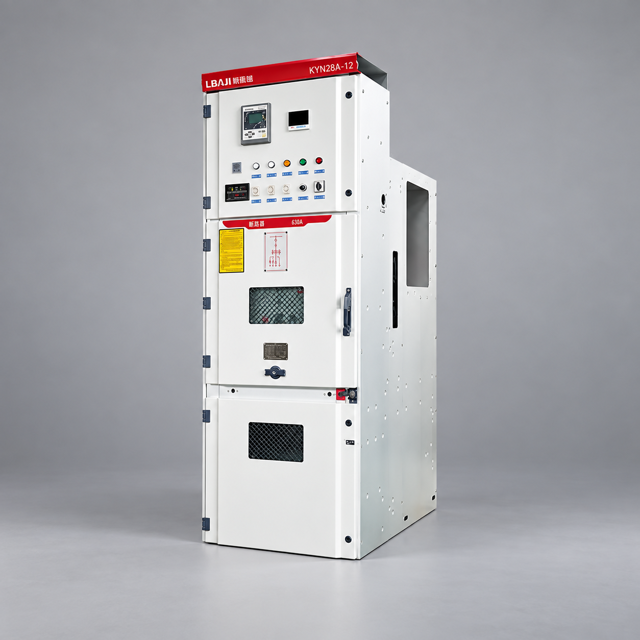
Do not rely on a control-screen indicator as proof of safe isolation. Do not open a sealed or interlocked compartment merely to reproduce a generic test. For equipment such as the LBAJI XGN15-12 metal-enclosed switchgear, the permitted access and test points depend on the exact configuration. The featured cabinet image shows its external form, not a test connection diagram. Our switchgear maintenance checklist
Insulation testing requires a defined setup
Before specifying insulation resistance or withstand testing, establish which components are connected, which electronics or surge devices must be protected, what voltage and duration are permitted, and what environmental conditions will be recorded. The instrument and leads must suit the equipment. A single resistance number without test voltage, temperature, humidity, circuit isolation and previous comparable results is weak evidence. Leakage and polarization behavior can have different meanings on different insulation systems. An inappropriate test can damage connected devices or give a misleading result.
For an installed medium-voltage assembly, separate switchgear insulation from the connected cable and transformer circuits when interpreting findings. If a result is abnormal, compare phases and historical baselines, confirm test setup, and isolate the affected section under the approved method. Do not raise the test voltage repeatedly to “get a pass.” Record the reason for any retest and the exact change made between readings.
Contact resistance and breaker operation
A high-resistance contact can heat under load. Measuring main-circuit or joint resistance may help identify degraded connections, but the result depends on the injection current, contact state, lead placement and temperature. Use the manufacturer’s accepted range and the same repeatable method for trend comparisons. A difference from previous results should trigger investigation, not an automatic replacement decision based on an arbitrary internet threshold. The Megger technical overview describes contact-resistance measurements on breakers, switchgear and busbars.
Breaker timing and travel tests assess whether opening and closing operations behave as designed. Pole spread, operating times, coil current and auxiliary-contact sequence may matter for a particular breaker. These measurements are not interchangeable across breaker models or test setups. The Megger breaker-testing explanation provides context on timing and contact measurements. A breaker that moves on command may still have an unacceptable timing trace; conversely, a number outside a generic example may be within the correct model limit.
Relay injection and scheme verification
Secondary injection applies simulated electrical quantities to a protection relay to verify its configured elements, pickup, timing and output logic. Primary injection may exercise more of the measurement chain, including CTs and wiring, but the method and risk differ. Decide which uncertainty needs to be resolved. Save the approved settings and as-found file before any change. Compare the installed version with the coordination study, then record the as-left settings, firmware and signatures. A technically correct relay test is not enough if the wrong setting group is active.
End-to-end checks matter because trip coils, breaker auxiliary contacts, interlocks, alarms and SCADA points can be miswired even when each device works on a bench. Build a test sequence that avoids unintended feeder trips or lost supervision. The OMICRON switchgear and breaker testing material summarizes several measurement families, but no single instrument or brand is a universal requirement. Our protection-relay guide
Sealed and low-voltage assemblies need different plans
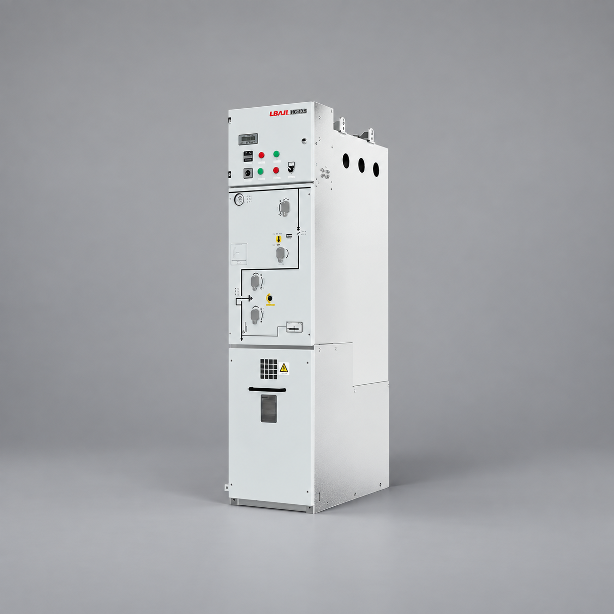
Do not open sealed primary compartments on a gas-insulated or fully insulated unit simply to perform an AIS-style inspection. Use its designated terminals, pressure or condition indicators and manufacturer-approved tests. The LBAJI HC-40.5 sealed ring-network switchgear has an enclosure architecture unlike an ordinary withdrawable metal-clad cubicle. A test plan must account for that difference and for the configuration’s actual insulation medium. “Sealed” does not make external cable or control circuits immune to faults.
Low-voltage switchgear can contain withdrawable drawers, multiple breaker frames, motor circuits and control electronics. The LBAJI MNS/GCK/GCS low-voltage lineup is a different test population from a medium-voltage RMU. Separate assembly checks from each feeder or motor starter’s functional tests, and protect sensitive devices when applying electrical tests. The test matrix should identify which drawers or compartments were actually tested, their positions, circuit IDs and as-left state. A single report line saying “switchgear passed” is not enough for a multi-bay assembly.

Record a test so it can be repeated and trusted
Each result should include asset ID and serial number, location, drawing revision, date, personnel, test instrument and calibration status, method, setup, environmental conditions, raw values, units, acceptance source and conclusion. Attach traces or settings files where appropriate. Keep “as found” and “as left” clearly separate. If a test is waived, record who approved the deviation and what alternate evidence supports energization. If a result fails, document the repair or engineering disposition and the subsequent retest rather than overwriting the original value.
A final commissioning package should reconcile every open item: temporary jumpers removed, links restored, correct relay group active, trip paths functional, covers secured, alarms normalized, operating labels accurate and authorization signed. Testing is complete only when the equipment is in its approved operational condition and the evidence can be traced to that exact assembly. It does not replace periodic inspection or future condition monitoring; it establishes a defensible baseline for them.
Further viewing: IIT Roorkee’s lecture explains classification and requirements for protective-relay testing. It provides educational context, not a test procedure for a specific switchgear model.