A ring main unit is a type of switchgear, so ring main unit vs switchgear is not a comparison between two completely separate equipment categories. The useful question is whether a particular RMU arrangement or another switchgear assembly better fits the required distribution circuits, protection, operating method and maintenance approach. An RMU is commonly associated with compact distribution arrangements, while switchgear is the broader term covering many assemblies and duties. This guide explains how to make a project comparison without assuming that every RMU or every conventional lineup has the same functions. It is not a field switching procedure.
Correct the category relationship
Switchgear broadly includes equipment used for switching, protection and control in an electrical network. An RMU falls within that category. Product catalogues sometimes contrast RMUs with metal-clad or other distribution switchgear, but that shorthand should not imply that an RMU is something outside switchgear. Identify the actual two proposed arrangements before comparing them.
A useful specification describes circuit functions, electrical duties, interfaces and operating requirements. A buyer asking only for an RMU may receive different combinations of switches, protection and other functions. A buyer asking only for switchgear faces an even broader set of possibilities. The responsible engineer should define what the network needs and require suppliers to map their proposals to those requirements.
Explain the distribution role without assuming a network topology
RMUs are often used at distribution points associated with ring or other compact feeder arrangements. The actual network can be operated in different ways depending on its approved design. The equipment name does not prove that a ring is continuously closed or that two sources may be paralleled. Those operating states belong to the network design and operating procedures.
Start the comparison with the single-line drawing and normal operating narrative. Identify incoming circuits, outgoing feeders, transformer circuits and any required alternate supply path. Record which circuit functions must be available in each position. That information is more useful than a general claim that one product family is always more reliable or always easier to operate.
| Comparison dimension | RMU proposal: confirm | Other switchgear proposal: confirm |
|---|---|---|
| Circuit arrangement | Required feeder and transformer functions are included | Proposed lineup maps to the same functions |
| Protección | Device and scheme match the circuit duty | Device and scheme match the same circuit duty |
| Space and access | Installation and maintenance space are documented | Full working and service space are documented |
| Interfaces | Cable, auxiliary and control interfaces are accepted | Cable, auxiliary and control interfaces are accepted |
| Mantenimiento | Approved instructions, access and support are available | Approved instructions, access and support are available |
| Verificación | Evidence applies to the proposed assembly | Evidence applies to the proposed assembly |

Compare functions rather than cabinet size
A compact cabinet can be useful where site space is constrained, but size alone does not determine suitability. Required protection, isolation, measurement and operating functions must still be present. Some arrangements use particular combinations of switching and protective devices. Others use different devices to meet the same project need. The comparison should identify the functions and the evidence for each proposal.
Do not assume that a visible handle performs every type of switching duty. Switching load current, providing isolation and interrupting faults are different functions. The actual device capabilities and operating requirements come from the equipment documents. This article avoids prescribing which device must be used in a particular circuit because that decision depends on the network design and applicable requirements.
Protection needs an actual scheme
The project should define the required protection behavior and coordination. The proposed RMU and alternative assembly may use different hardware arrangements, but each must meet the approved scheme. Ask the supplier to identify the protective devices, measurements and interfaces included in its scope. A product-family label is not a protection study.
For circuits that use relays, identify the settings owner and the configuration deliverables. For other protective arrangements, request the relevant selection and coordination basis. The comparison should not treat factory defaults or a standard brochure configuration as the approved network solution. The responsible engineer must review the actual arrangement and define the appropriate verification.
Insulation and enclosure are separate comparison dimensions
RMUs and other switchgear can use different insulation and enclosure arrangements. Those choices affect installation, handling, maintenance and other project considerations. Do not infer a particular insulating medium from the letters RMU alone or from a closed cabinet photograph. Request the offered product’s actual construction and the related instructions.
Where a proposal includes an insulating gas, the supplier should identify it and explain applicable handling and service requirements. Avoid broad environmental claims that are not tied to the actual configuration. Where a proposal uses another arrangement, obtain its relevant installation and maintenance requirements as well. Compare documented project consequences rather than assuming that one technology automatically wins every criterion.

Maintainability depends on the design and site
Some assemblies are designed around withdrawable devices; others use fixed arrangements or different service methods. Confirm the actual design instead of treating all non-RMU switchgear as withdrawable. Review what work can be performed, what equipment or specialist support is required and how an outage is planned under the approved procedures.
The operating organization should assess the consequences of a device or compartment becoming unavailable. Ask about approved replacements and relevant spare support. A compact initial installation can still have a demanding replacement path. Conversely, a larger lineup is not automatically easier to maintain. The comparison should use the manufacturer’s instructions and the site’s maintenance strategy.
Check cable and control interfaces early
Both proposals must fit the actual cable system and project interface requirements. Document the termination arrangement, cable access and responsibilities. Do not infer compatibility from a similar connection shape. The supplier should provide the interface information needed by the cable designer and installer before the equipment is ordered.
Auxiliary power, indications, remote commands and communications also need a defined scope. An RMU can be supplied with different levels of automation depending on the design. Another switchgear assembly may also provide those functions. Compare the specific hardware, configuration and integration responsibilities. The presence of a communications port alone does not establish completed remote-control capability.
Review installation space beyond the footprint
Request the arrangement drawings and required working, operating and maintenance space. Door movement, cable routes and equipment handling can affect the usable installation. A footprint dimension without those requirements is incomplete. The civil and electrical design teams should review the full arrangement together.
The LBAJI XGN15-12 exterior used in the illustrations provides a real RMU cabinet reference. It shows visible front-panel arrangements rather than a complete project installation. The product image cannot establish internal clearances, ratings or maintenance access. Obtain the project-specific drawings and instructions before accepting a site layout, and do not scale measurements from the illustration.
Compare verification evidence on the same basis
The relevant assembly evidence should support the actual proposed equipment and duties. Ask each supplier to identify the applicable standards and document scope. The IEC metal-enclosed AC switchgear publication provides a standards context for equipment within its stated range, but the project must determine its complete requirements and applicable editions.
A component certificate or general quality certificate is not a substitute for the relevant assembly evidence. If a proposed arrangement differs from the configuration described in a document, request an explanation of how the evidence applies. Keep limitations and unanswered questions visible. This makes the comparison reviewable rather than reducing it to a list of certificates without a connection to the ordered equipment.

Use a project example without inventing ratings
Consider a distribution point that needs two feeder positions and a transformer circuit. The engineer defines the permitted operating states and protection needs. One supplier proposes an RMU arrangement and another proposes a different metal-enclosed lineup. The buyer compares their circuit functions, interfaces, required space, verification and support against the same design basis.
Neither arrangement should be accepted solely because it matches the number of visible front panels. A panel count does not establish the device functions inside. If one proposal leaves a function to external equipment, include that equipment and its interfaces in the comparison. The example illustrates the review method; it is not a recommendation for a universal circuit or a specific product configuration.
Compare cost after technical scope is resolved
An initial equipment total can hide differences in civil works, cable interfaces, auxiliary equipment, documents and integration. Build a common scope and record deviations before comparing prices. State the delivery and site-work boundaries consistently. This guide does not provide unsupported price ranges or claim that every RMU is cheaper than every other switchgear assembly.
Review the operating implications too. Spare support, maintenance instructions, service availability and expected outage arrangements can affect a project’s cost and continuity. Use supplier evidence and the operating organization’s needs to assess those items. A purchase decision should reflect an accepted technical arrangement and clear commercial scope rather than a generic equipment-family preference.
Make the final selection traceable
Record the design basis, proposals reviewed, accepted deviations and the reasons for selection. Keep the final arrangement and interface drawings available to the installation and operating teams. Identify the factory and site acceptance requirements before manufacture. Design verification, factory checks and commissioning remain distinct parts of the project.
Qualified personnel must operate and maintain the installed equipment under applicable rules and procedures. The linked electrical work-practice requirements provide one safety framework for relevant U.S. work; local requirements may differ. This comparison helps a buyer ask better specification questions. It does not authorize field operations or replace approved equipment instructions.
Preguntas frecuentes
Is an RMU different from switchgear as a whole?
An RMU is a type of switchgear. The useful comparison is between a specific RMU arrangement and another proposed switchgear assembly.
Does ring main unit mean a ring must stay closed?
No. Allowed network operating states come from the approved design and procedures, not the product name.
Are all RMUs gas-insulated?
Do not infer construction from the category name. Confirm the actual offered insulation arrangement and its instructions.
Is compact equipment always the best choice?
No. Circuit functions, protection, interfaces, service space, verification and maintenance requirements must also be satisfied.
What should be compared before price?
Resolve the equipment functions, duties, installation interfaces, verification evidence and supplier responsibilities so that prices describe comparable scopes.
Referencias técnicas y equipo relacionado
Las páginas de estándares vinculados describen su alcance; la conformidad con el proyecto requiere los documentos aplicables y una revisión técnica.
- Ámbito de aplicación de los disipadores de calor de metal de IEC para equipos de transformación de CA
- 29 CFR 1910.333 prácticas de trabajo eléctrico (versión oficial de 2025)
- LBAJI XGN15-12 Unidad central de anillo
- Fundamentos de la automatización de la planta eléctrica
- Verificación y prueba de los equipos de control
- Planificación de mantenimiento de equipos de control
Formación adicional: fundamentos de la maquinaria
Este vídeo educativo independiente complementa el análisis de las funciones de los equipos. No sustituye a los documentos de proyecto aprobados ni a los procedimientos de trabajo eléctrico cualificados. Fuente: Gaurav J – TheElectricalGuy.
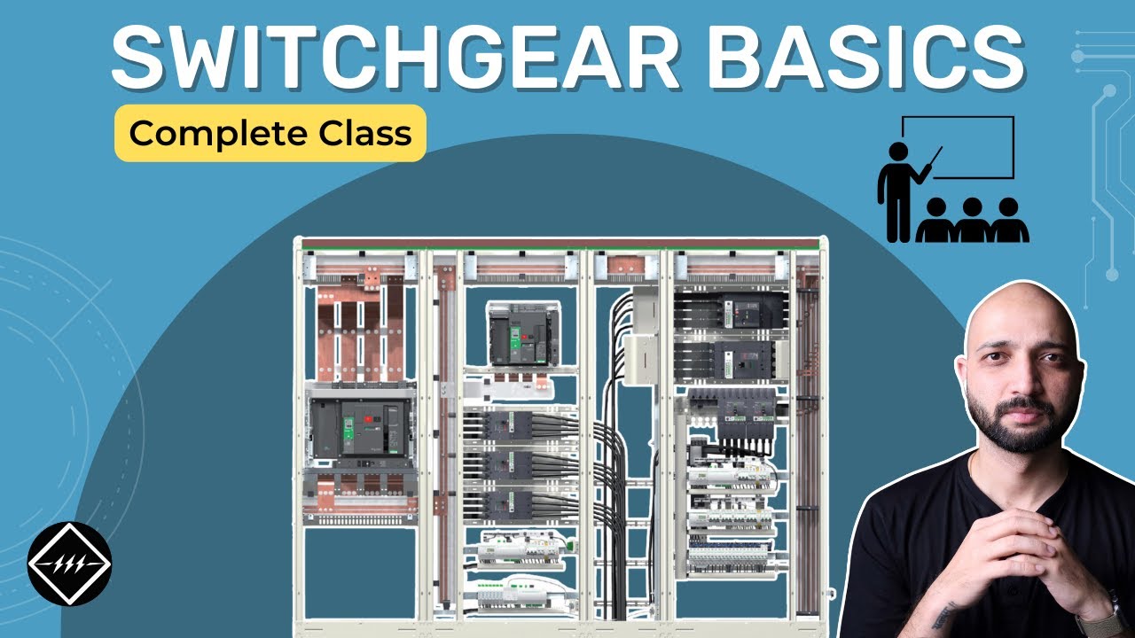
Mira los conceptos básicos de los equipos de control | TheElectricalGuy