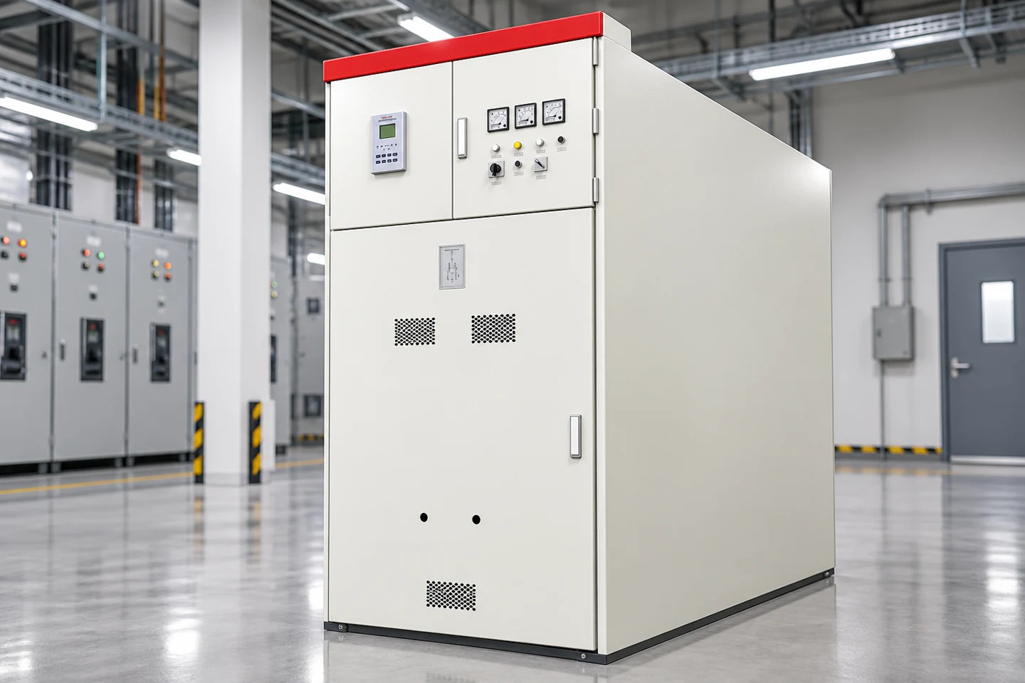
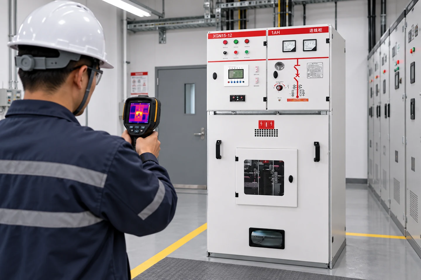
Custom electrical control panels are engineered assemblies that house power switching, control, protection, measurement and communication devices for a defined machine or distribution system. A good custom panel is not simply a standard enclosure with extra components. It is a documented system whose ratings, heat management, wiring, software interfaces and safety functions match the load and the site. This guide explains how to turn an application requirement into a buildable panel specification and how to verify the finished assembly.
Start with the control and power boundary
Write down what the panel receives, what it controls and where responsibility changes to another assembly. A panel may accept a feeder and distribute power to motors, or it may only switch 24 V control circuits while a separate switchboard handles the line current. Identify supply voltage and frequency, available fault current, prospective load, motor starting method, control voltage, short-circuit rating, grounding arrangement and environmental conditions. Also list every load that can start at the same time and every source that can backfeed the panel.
Separate power, control, safety and communication functions in the design. A motor starter, PLC I/O, emergency-stop circuit and Ethernet switch may share an enclosure but do not share the same design assumptions. The IEC 61439 series provides a framework for low-voltage switchgear and controlgear assemblies; the applicable part, local code and certification route must be chosen for the actual assembly. A custom panel drawing should state which standard and edition are being used, rather than implying that every panel follows one universal rule.
| Design input | What to define | Why it affects the panel |
|---|---|---|
| Supply and fault duty | Voltage, frequency, phases, SCCR or short-circuit current and upstream protection | Sets bus, breaker, fuse, conductor and enclosure requirements |
| Loads | Motor, heater, drive, valve, instrument and spare circuits | Determines current, starting behavior, protection and heat |
| Control philosophy | Local/remote modes, sequence, permissives, alarms and reset behavior | Defines PLC, relay, terminal and HMI interfaces |
| Entorno | Indoor/outdoor, dust, moisture, corrosion, altitude and ambient temperature | Changes enclosure, cooling, finish and component derating |
| Mantenimiento | Access side, isolation points, test points, spares and lifting limits | Influences layout, labeling and safe serviceability |
Choose the enclosure and internal arrangement
Choose enclosure material and ingress protection from the site, not from appearance. Painted steel may suit a clean indoor room; stainless steel or a suitable coating may be needed in a corrosive or washdown area. An outdoor panel may need a roof, sun shield, heater, thermostat, drain and anti-condensation measures. The enclosure size must leave working space around terminals, bend radius for cables, separation between circuits and room for heat-producing components. A cramped panel can pass a visual inspection and still fail in service because terminals loosen or drives overheat.
Arrange components by function and service access. Keep incoming isolation and protective devices identifiable. Group contactors, overloads and drives so their heat and wiring are manageable. Put low-voltage signal and communication wiring away from high-current or high-frequency conductors where the design requires it. Provide a documented protective-earth path and bond doors, gland plates and removable metalwork as required by the design. A panel layout drawing should show component references, wire numbers, terminal strips, spare space and cable entry, not only a front elevation.
Specify breakers, contactors and control devices
Protective devices should be selected from the load characteristics and coordination study. A motor circuit may need short-circuit protection, overload protection, phase-loss or imbalance monitoring and a contactor suitable for the duty category. A heater circuit may require a different switching device and thermal design. Drives and power supplies can have inrush and harmonic behavior that affects upstream protection. Do not copy a breaker size from a similar-looking project without checking conductor ampacity, fault duty, selectivity and the equipment manufacturer’s instructions.
Define the PLC or controller by the required I/O type and future capacity. Digital inputs may need dry contacts or a defined voltage; analog signals need range, resolution, shielding and reference. Safety inputs and outputs should be designed for their required performance level or category rather than mixed casually with ordinary control I/O. Network ports need an addressing, segregation and loss-of-communication response. The OSHA lockout/tagout requirements are a reminder that control logic never replaces physical energy isolation and an approved safe-work procedure.
Thermal design and power quality
Estimate heat from drives, power supplies, contactors, relays, transformers and network devices at the expected operating load. Add the heat of the enclosure in its actual mounting position and ambient temperature. Natural convection may be sufficient for a small panel; a fan-filter, heat exchanger or air conditioner may be needed for a dense outdoor or sealed enclosure. Cooling equipment also introduces dust paths, condensate and maintenance requirements. Record the assumed ambient, duty cycle and component spacing so a later change can be assessed.
Consider voltage drop in control wiring, inrush from power supplies, electromagnetic interference from drives and the effect of long sensor cables. Use shield termination and routing that match the signal type and manufacturer’s guidance. Keep a clean 0 V or reference strategy for analog and communication circuits. Do not promise a particular temperature rise or noise level until the actual component data and enclosure calculation support it.
Drawings, labels and the build package
A complete custom-panel package normally includes a single-line diagram, power schematic, control schematic, I/O list, terminal plan, panel layout, bill of materials, wire schedule, nameplate schedule, software or parameter backup and test plan. Show the drawing revision on every controlled sheet. Assign a unique reference to each device and use the same reference on the physical label, schematic and spare-parts list.
Use labels that remain readable after installation and maintenance. Identify incoming sources, isolation points, voltage levels, terminals, fuses, protective-earth points and hazardous energy. Include warnings that are true for the exact assembly; avoid generic labels that imply a feature the panel does not have. A clear terminal schedule prevents a common commissioning error: wiring a correct device to the wrong signal because the field cable number and panel terminal number were never reconciled.
Factory inspection and commissioning
Before energization, inspect workmanship against the approved drawings. Check conductor routing, ferrules, torque records, protective-earth continuity, component part numbers, spare ways, labels, door operation and enclosure sealing. Verify that protective devices match the schedule and that factory settings are recorded. Test control power polarity and each input/output using a controlled procedure. A relay or PLC simulation does not prove that the final field device, cable, interlock and actuator operate together.
Functional tests should cover normal start/stop, permissives, trips, emergency stop, loss of control power, remote/local transfer, alarm reset, communication loss and recovery. Record as-found and as-left settings. For an assembly connected to a distribution system, coordinate tests with the approved protection study and switching plan. Our Guía de pruebas de equipos de control explains why a single insulation reading or relay test is not a complete acceptance program.
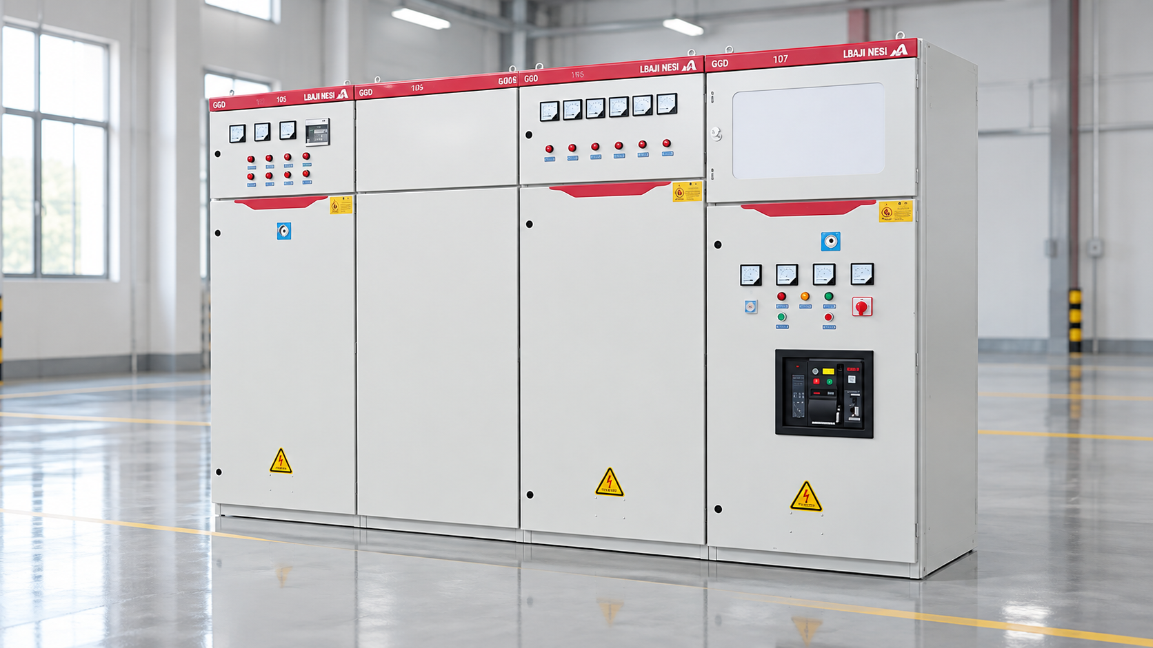
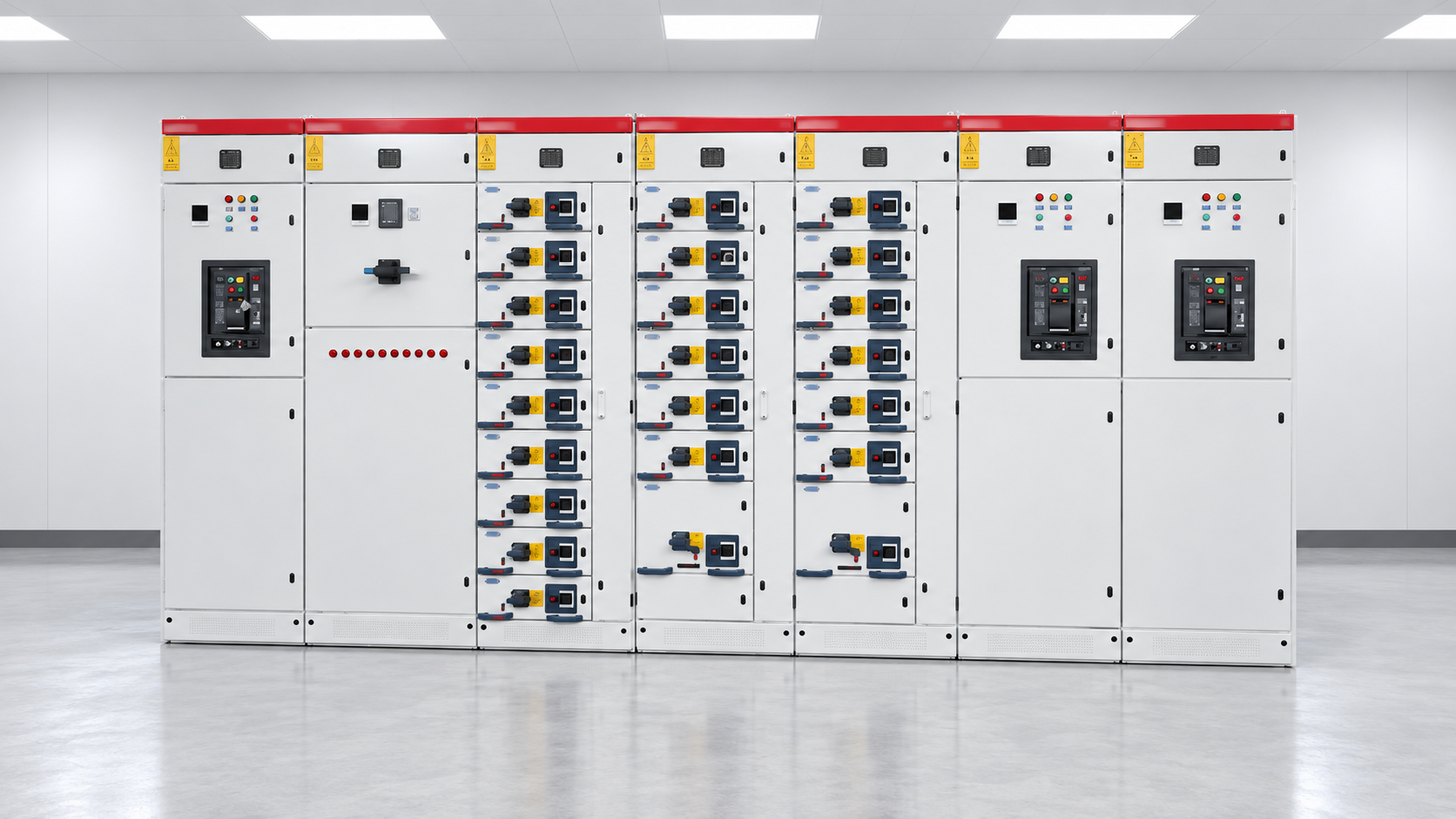
El LBAJI GGD low-voltage switchgear is an example of a product family that can form part of a low-voltage distribution solution; the final custom configuration still needs its own drawings, ratings and test record. For modular withdrawable applications, compare the required functions with the LBAJI MNS/GCK/GCS lineup and confirm the ordered arrangement rather than inferring it from a catalog photograph.
How to request a comparable quotation
Give each supplier the same load list, single-line, control narrative, I/O list, environmental data, short-circuit duty, enclosure constraints, required standard, communication interfaces, spare capacity and documentation requirements. Ask the quotation to identify assumptions and exclusions. Request a general arrangement and heat calculation before approving manufacture. Require a drawing review stage so wiring and terminal changes are resolved before fabrication.
A useful handover includes approved drawings, marked-up as-built copies, test records, software backups, parameter files, certificates where applicable, recommended spares and a maintenance schedule. Keep the delivered serial number and revision with the asset register. This makes future modifications safer and avoids treating a one-off custom panel as an undocumented black box.
Further viewing: Eaton’s neutral electrical-distribution training on reading one-line drawings helps explain how panel functions are represented; it does not replace the drawings or procedures for a custom assembly.