Switchgear busbar sizing starts with the assembly’s continuous-current duty, installation conditions and short-circuit requirements. A copper or aluminium cross-section alone does not establish an acceptable switchgear rating. The manufacturer must verify the conductor arrangement, joints, supports, enclosure and relevant interfaces as an assembly. For a buyer, the useful output is a documented connection between the project duty and the offered construction, rather than an isolated amperes-per-square-millimetre rule.
This guide explains how to prepare that review without pretending that a generic calculator can approve a live installation. It concerns busbars inside switchgear; cable sizing, external busway design and utility network studies require their own assessments. Any physical examination or alteration belongs under an approved electrical safety procedure by qualified personnel.
Start with the current path and operating duty
Identify which conductor is being assessed. Main horizontal bars, vertical distribution bars, circuit connections, neutral conductors and protective conductors perform different functions. A lineup may contain several arrangements with different ratings. An overall enclosure model number cannot identify every current path inside it.
Prepare a single-line diagram with source ratings, feeder duties, expected loading and permitted operating configurations. Record whether parallel incomers or a bus coupler can change the current through individual sections. An emergency transfer arrangement may create a duty that the normal configuration never reaches. Review the credible operating cases rather than simply adding every connected load.
Demand factors, diversity, cyclic loading and future allowance must come from the project design basis. A supplier should see the applicable assumptions and their approval status. If an expected future load is speculative, distinguish the reserve requirement from confirmed demand so that proposals can be compared consistently.
Why cross-section is only one input
For a rectangular conductor, cross-sectional area is width multiplied by thickness, expressed in consistent units. Multiple parallel bars add geometric area, but that arithmetic does not prove equal current sharing or establish their assembled thermal performance. Spacing, orientation, joint design and magnetic effects influence the result.
Electrical losses create heat; the assembly must transfer that heat to its surroundings without exceeding applicable limits. A bar in open air and the same bar inside a compact enclosure do not necessarily have the same usable duty. Nearby conductors, insulating barriers and connected devices can change the local temperature conditions.
Material selection also matters. Conductivity, surface condition, joint preparation, compatible connections and mechanical characteristics form part of the manufacturer’s design. Do not substitute aluminium for copper by matching only the visible dimensions. Nor should a buyer demand a larger bar while leaving supports, clearances and the verification basis unchanged.
Establish the service conditions
Ask for the ambient temperature assumptions, altitude, installation location, enclosure protection and ventilation arrangement used for the offered rating. Match these to the actual switchroom conditions. The surrounding air may be warmer than the outdoor design value when several heat-producing assemblies occupy a confined room.
Natural ventilation, forced ventilation and a sealed enclosure are different design cases. Filters, insect screens or changes made during site installation can affect airflow. A rating that depends on fans requires an agreed response to loss of ventilation, appropriate maintenance and a clear statement of the permitted operating condition.
Harmonic loading and neutral duty require explicit attention where relevant. Nonlinear loads can change the relationship between phase and neutral currents. The design engineer should establish the required assessment rather than assuming that a neutral conductor can always be reduced or that phase current alone describes the installation.
Use a duty-to-evidence review table
Contexto de referencia: IEC 62271-1 common specifications scope. Esta lista de verificación cualitativa original organiza las decisiones relacionadas con el proyecto; no se trata de una norma reproducida ni de un sustituto de los criterios aprobados.
| Elemento de revisión | Required project input | Evidence to obtain |
|---|---|---|
| Corriente continua | Approved operating cases and load assumptions | Assembly rating and applicable temperature-rise verification |
| Conductor arrangement | Material and proposed geometry | Controlled drawing including parallel bars and connections |
| Entorno | Ambient, altitude and enclosure conditions | Stated service limits and any manufacturer derating |
| Short-circuit duty | Prospective fault level and clearing time | Short-time and peak withstand evidence for the assembly |
| Neutral duty | Load characteristics and harmonic assessment | Neutral arrangement and applicable verification |
| Site modifications | Final cable and interface requirements | Written approval and assessment of affected verification |
The table is a document review tool, not a list of universal acceptance values. Agree the governing standard and project criteria before comparing the proposals. IEC 62271 documents address high-voltage switchgear and IEC 61439 documents address low-voltage assemblies within their respective scopes; they should not be treated as interchangeable rating labels.
Separate continuous heating from fault withstand
A busbar must meet normal service requirements and the applicable fault duty. Continuous-current adequacy does not prove that its supports and joints will withstand a short circuit. Fault current creates thermal and mechanical stresses over a different time scale from normal load heating.
The short-time withstand assessment needs both current and duration. The peak withstand assessment addresses a different part of the duty. Obtain the manufacturer’s applicable declared values and their verification basis, then have the project engineer compare them with the fault study and protection clearing assumptions.
Do not use a thermal screening expression as a complete mechanical design. The strength and spacing of supports, conductor arrangement and connection details matter. A different bar size may change forces and clearances as well as losses. Approval must apply to the offered construction, including relevant joints and transitions.
Understand what verification actually covers
Request enough information to identify the tested or otherwise verified assembly and explain its relationship to the proposal. Useful identifiers include drawing revision, enclosure arrangement, conductor layout, connection details, relevant devices and the applicable verification method. A report title without construction identity is difficult to evaluate.
For temperature-rise evidence, review test conditions, current paths, measurement locations and the manufacturer’s interpretation of the results. Where design rules or comparisons are used under the governing standard, the manufacturer should explain the permitted relationship and its limits. A buyer should not invent an equivalence between visibly similar cabinets.
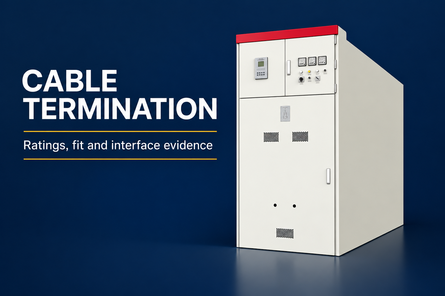
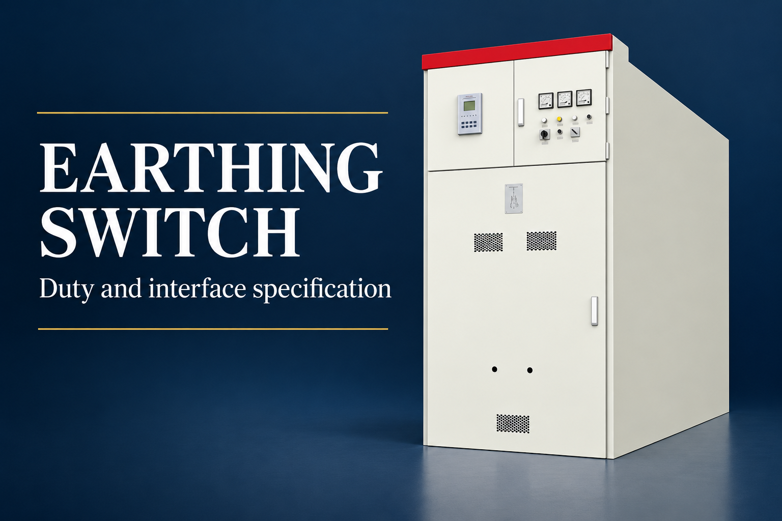
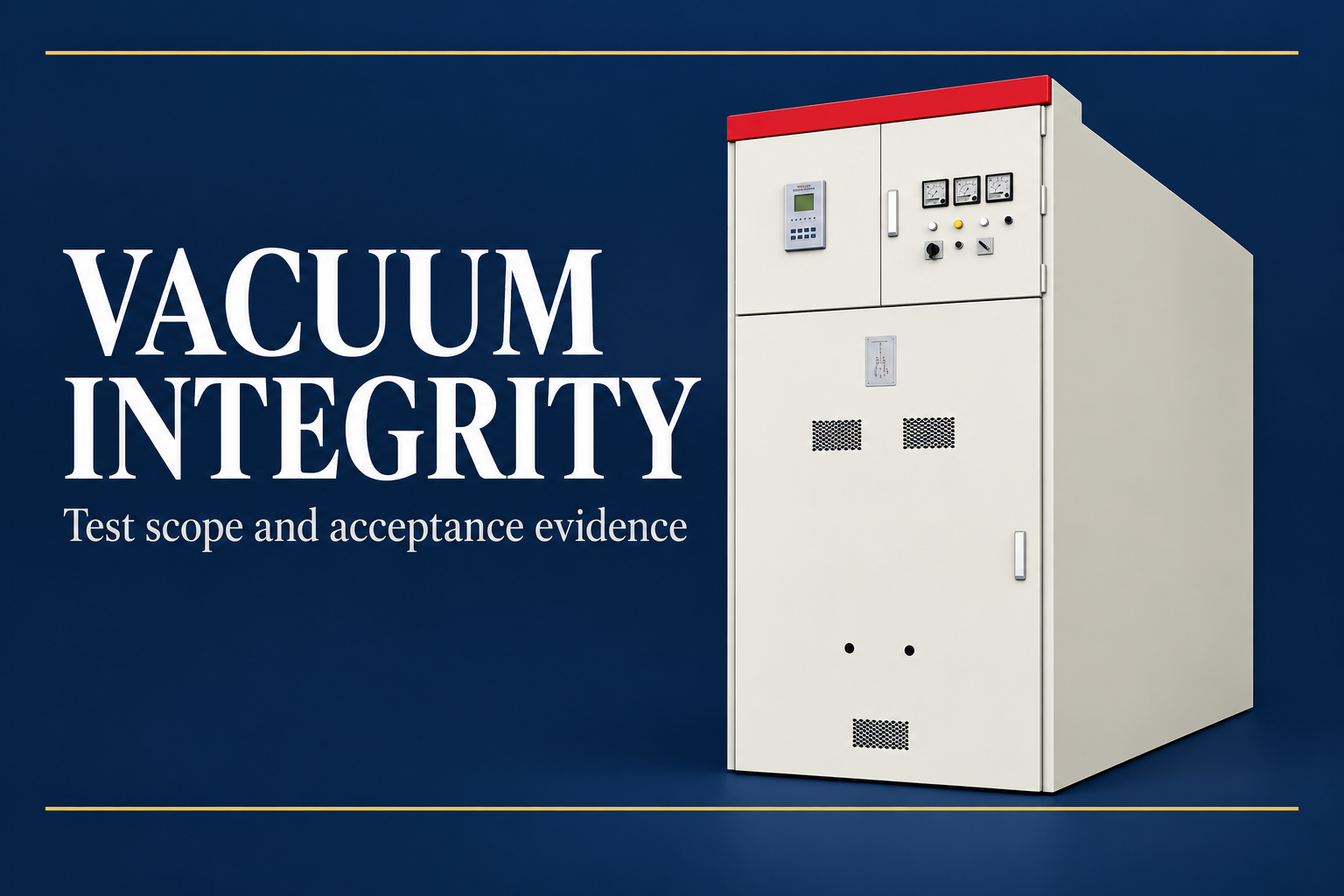
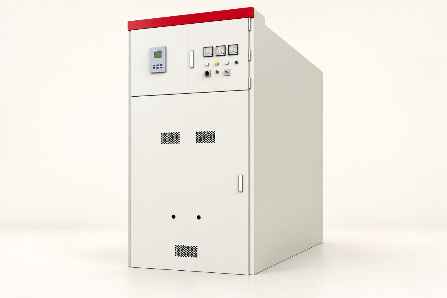
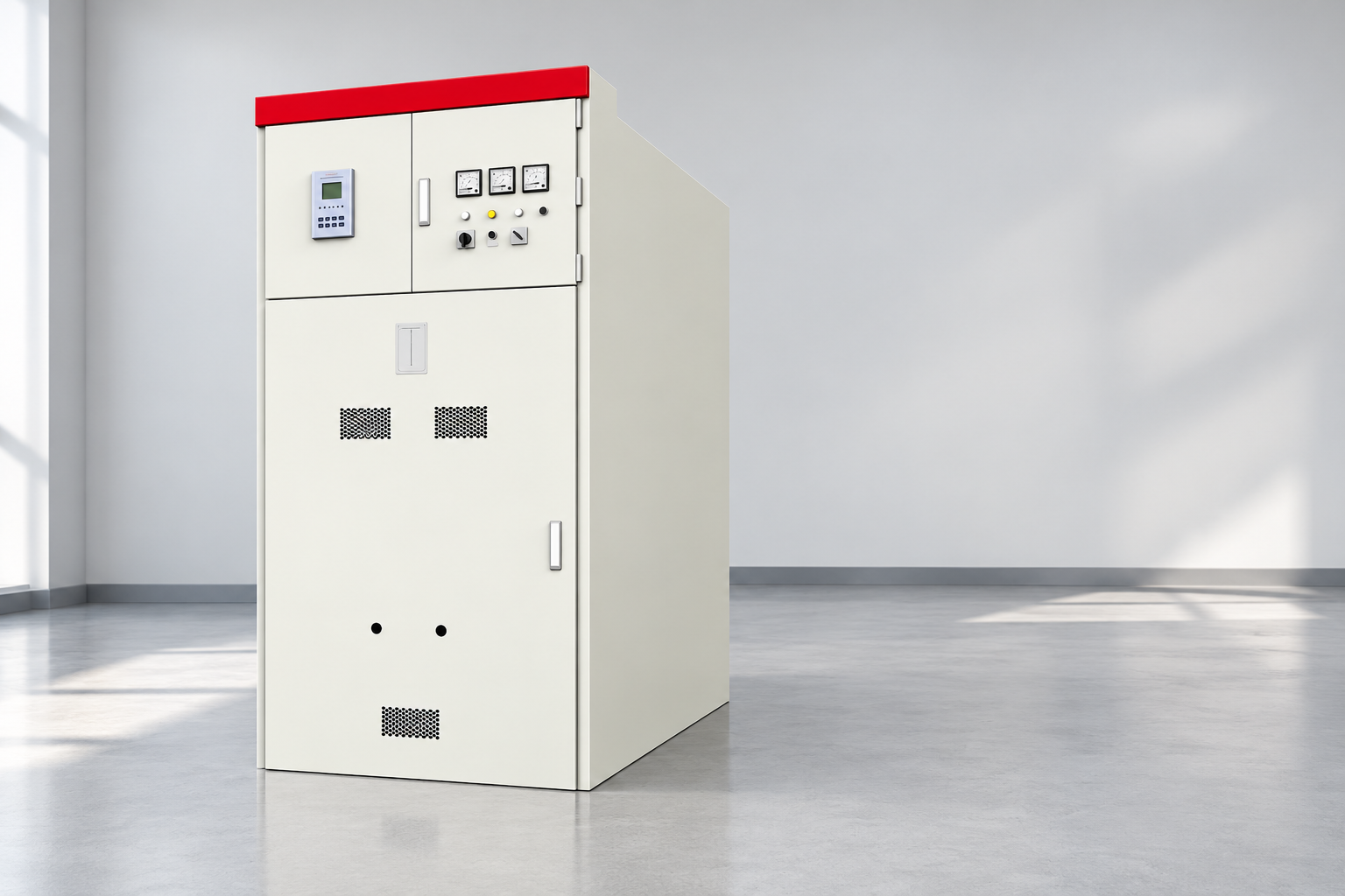
Catalogue photographs are useful for recognizing the equipment family but cannot establish internal conductor size, joint construction or thermal compliance. The KYN61 exterior illustrations in this article deliberately show closed equipment. Request the project-specific internal documents rather than inferring unseen details from those pictures.
A practical comparison example
Consider two offers for an industrial switchgear lineup. Both declare the same continuous current, but one uses a ventilation-dependent arrangement while the other quotes a different enclosure configuration. The proposals are not yet comparable, even if their visible bars have similar dimensions. First align the installation and operating assumptions.
Suppose the project also permits a coupler to transfer the entire load to one source. Mark the resulting current path and ask whether each affected section retains the required duty in that configuration. Review protection clearing time separately for the corresponding fault case. A normal-load comparison cannot answer the fault question.
The useful decision is a traceable acceptance record: this assembly revision meets this approved duty under these conditions, with these interfaces. If evidence is missing, retain a specific hold point. Replacing the missing evidence with a larger nominal cross-section could increase cost while leaving the actual uncertainty unresolved.
Common purchasing mistakes
A frequent mistake is specifying a fixed current-density value without the conditions that make it relevant. Such a rule can be a preliminary estimate within a defined design method, but it does not replace assembly verification. Ask what assumptions generated the proposed dimensions and what confirms their final suitability.
Another mistake is comparing only the main busbar while overlooking risers, connections or device terminals. A current path includes transitions and interfaces. The declared assembly duty must remain credible through those components. A larger main conductor does not automatically remove a limitation elsewhere.
A third mistake is authorizing site drilling, extra connections or substitute supports as minor installation work. These changes can affect contact performance, clearances and mechanical duty. Obtain written manufacturer review before implementing a modification, and update the controlled drawings and verification record as necessary.

Prepare a useful request for quotation
Provide the system voltage and frequency, approved continuous duties, fault study values and clearing assumptions, service conditions, enclosure requirements and installation arrangement. Include source and coupler operating cases, cable interface needs, neutral requirements where applicable and the intended future expansion boundary.
Ask the supplier to state the offered ratings, conductor material, relevant arrangement drawings, verification references and exclusions. Request a clear explanation of any forced-cooling dependency or site-condition limitation. The objective is to compare supported assemblies, not to collect unrelated busbar dimensions from different catalogues.
Allocate responsibility for final engineering review, drawing approval, factory checks and site acceptance. An agreed document schedule should identify which evidence is required before manufacture and which records accompany delivery. Resolve technical deviations before the purchase order makes the design difficult to change.
Keep the accepted arrangement controlled
At handover, retain the final drawings, applicable rating documents, verification references, approved deviations and operating limitations. The maintenance team needs to understand which construction and service conditions underpin the rating. A folder of unsigned preliminary drawings is not an adequate substitute for the accepted record.
If loading, ventilation or connected sources change later, reassess the affected duty before assuming the original margin remains available. The review should include the complete current path and the protection assumptions. Replacement parts and connection practices should follow the manufacturer’s instructions for the installed assembly.
Busbar sizing is therefore a coordinated design and evidence task. Start with the duty, evaluate the conductor arrangement within its enclosure, verify normal and fault conditions, and keep the accepted configuration traceable throughout the equipment’s service life.
Preguntas frecuentes
Is busbar cross-sectional area enough to choose a switchgear current rating?
No. Area is one geometric input. The conductor arrangement, connections, enclosure, service conditions and applicable assembly verification determine whether the offered equipment is suitable.
Can a generic copper busbar calculator approve my installation?
A calculator may support preliminary screening under stated assumptions. It cannot independently approve the complete switchgear assembly, its fault withstand or its installation interfaces.
Why must short-circuit duty be checked separately?
Fault duty creates short-duration thermal and mechanical stresses. Continuous-current adequacy does not prove the required short-time or peak withstand of the bars, supports and joints.
Can a supplier change busbar material without further review?
A material substitution requires assessment of the affected construction, connections and verification basis. Matching nominal dimensions does not establish equivalent performance.
What should buyers request before accepting the proposal?
Request the approved duty assumptions, controlled arrangement drawings, declared assembly ratings, applicable verification references, service limits and a clear record of technical deviations.
Fuentes técnicas y equipo relacionado
Las páginas estándar del catálogo establecen el alcance del documento; la conformidad y la aceptación requieren la revisión completa de los documentos aplicables y la ingeniería del proyecto.
- IEC 62271-1 common specifications scope
- IEC 61439-1 low-voltage assembly scope
- Copper for Busbars: Guidance for Design and Installation, copper industry technical guide
- UK HSE HSG85: Electricity at work, safe working practices
- LBAJI KYN61-40.5 Armadura de interruptores de metal desmontable con conexión eléctrica
- Fundamentos de la tecnología de automatización de la planta eléctrica
- Verificación y prueba de los equipos de control
- Lista de verificación de mantenimiento de la instalación de automatización
Formación adicional: formación técnica
Este vídeo educativo independiente explica los principios de medición o el contexto técnico de los equipos mencionados anteriormente. No muestra un procedimiento de trabajo seguro para el montaje específico. Fuente: Gaurav J – TheElectricalGuy.
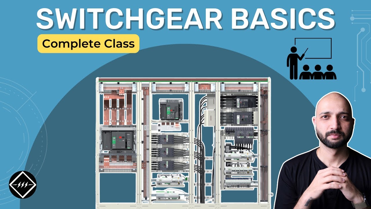
Mira los conceptos básicos de los equipos de control | TheElectricalGuy