What is a feeder in electrical distribution? In building wiring, a feeder is the set of circuit conductors between a supply source—such as service equipment or a separately derived transformer system—and the final overcurrent device that protects branch circuits. In utility distribution, “feeder” often refers to a medium-voltage circuit leaving a substation to supply a service area. Those uses are related but not identical; the drawing, equipment schedule and governing rules should make the intended boundary clear. Understanding that boundary helps engineers choose switchgear, cables, protection and panels without confusing a feeder with a final circuit to a load.
Two common meanings of feeder
El U.S. OSHA electrical definitions describe a feeder by its position between the source and the final branch-circuit overcurrent device. In a facility, a main switchboard may feed a distribution panel through a feeder; the circuits leaving the panel’s final branch breakers are branch circuits. A feeder can include a phase conductor set and any required neutral, grounding conductor and associated wiring method. The exact conductor arrangement depends on the system and code, not on the word “feeder” alone.
On a utility network, a distribution feeder is a circuit carrying power out of a substation toward primary distribution circuits and their transformers. The OSHA electric-power glossary describes distribution feeder circuits from substation output terminals to primary-circuit inputs, including examples of underground exit cables and overhead primary circuits. A utility engineer may therefore call an 11 kV outgoing circuit a feeder even though the facility-wiring definition above is written around branch-circuit protection. Always state the system context when using the term in an equipment specification.
Follow power from source to loads
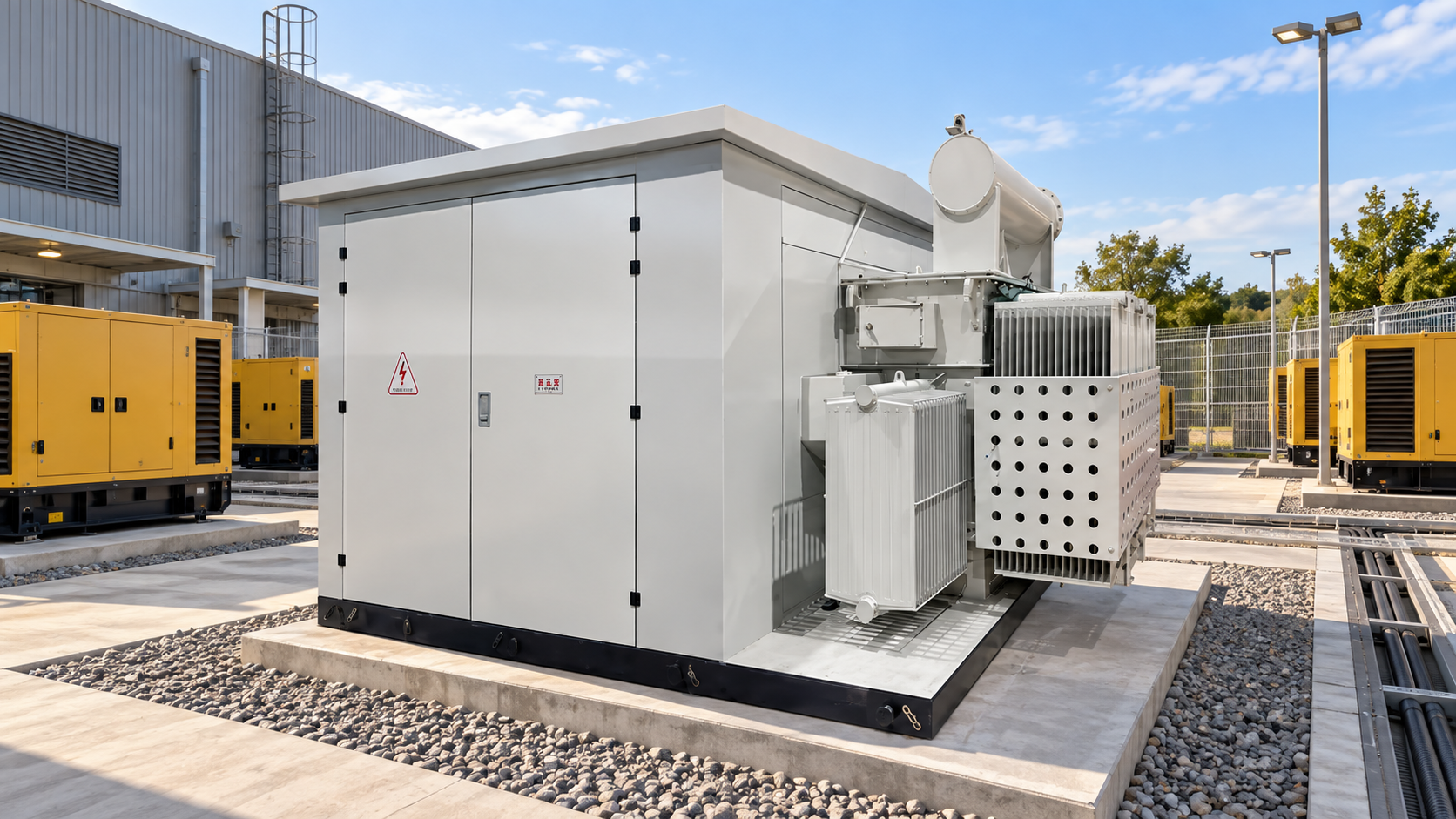
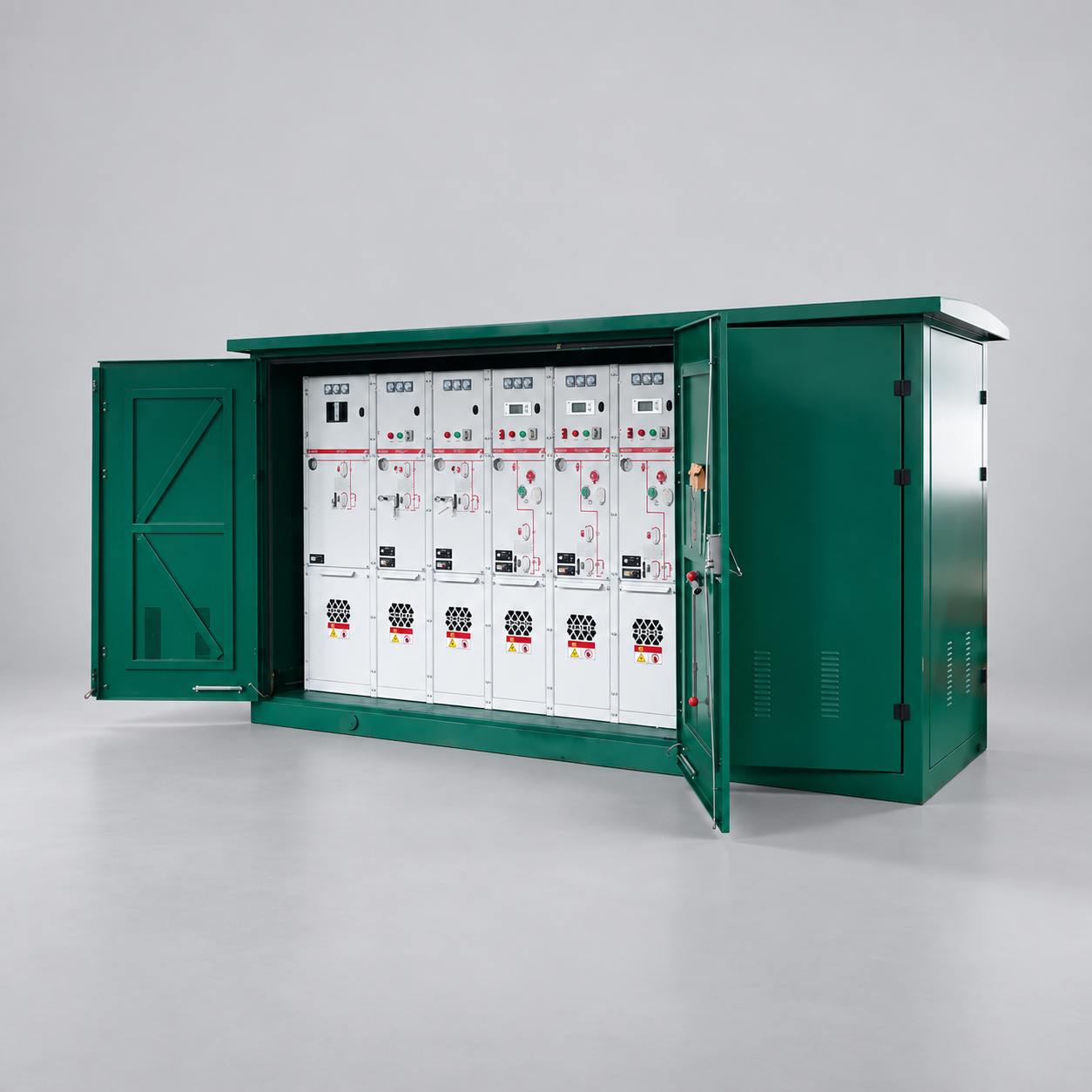
Consider a simplified path: a substation transformer supplies an 11 kV switchgear lineup; an outgoing breaker supplies a medium-voltage feeder; a distribution transformer steps voltage down; low-voltage switchgear supplies one or more panel feeders; final branch breakers then supply loads. This is only a conceptual chain. Real systems may contain ring mains, multiple sources, transfer schemes, embedded generation and several stages of feeder protection. A single-line diagram, not a generic paragraph, should show the actual topology. The featured image shows an LBAJI YBM-12 prefabricated substation as one possible distribution-equipment setting, not a diagram of its actual feeder connections.
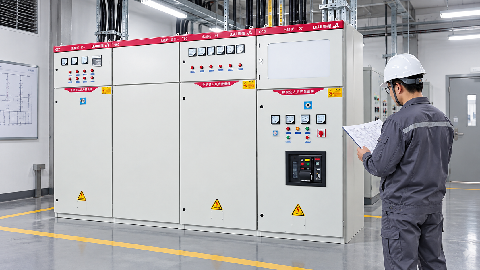
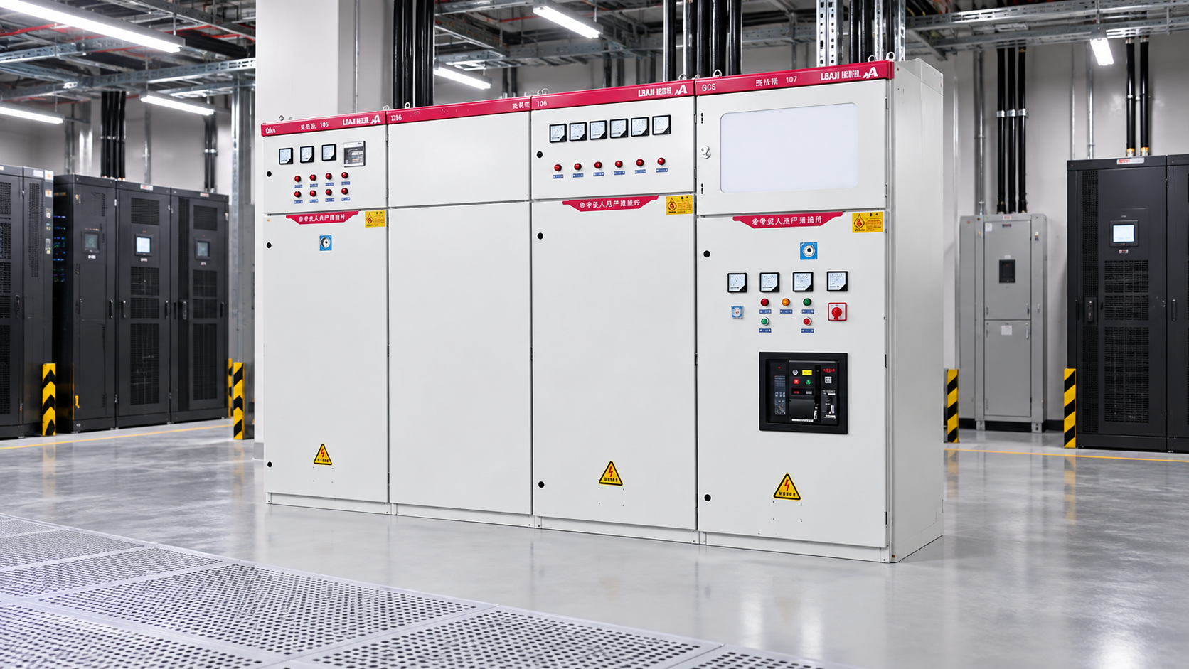
A Aparamenta blindada metálica KYN28A-12 may be specified for an outgoing medium-voltage feeder position where its ordered ratings and protection package suit the design. The cabinet photograph below shows the product family; it cannot tell us which breaker is an incomer or outgoing feeder in a particular lineup. Those roles are defined by the project single-line diagram and the as-built labels.
Feeder, branch circuit, service and lateral compared
| Term | Typical position | Key distinction |
|---|---|---|
| Service conductors | Supply connection to service equipment, as defined by the jurisdiction | They are not automatically the same as downstream feeders |
| Building feeder | Source or service equipment to the final branch-circuit overcurrent device | May supply a panel or other distribution equipment |
| Branch circuit | Final overcurrent device to outlet or utilization equipment | Ends at the load-side usage points under the applicable definition |
| Utility distribution feeder | Distribution substation outward to the primary distribution network | Utility term for a network circuit or service area |
| Lateral | Branch off a main distribution feeder | Common utility topology term, not a substitute for the facility wiring definition |
In the U.S. workplace context, OSHA’s branch-circuit interpretation quotes the distinction between final overcurrent protection and outlets. Other codes and jurisdictions may draw boundaries differently. The table is a vocabulary aid, not a universal legal classification. If a drawing calls a circuit “feeder F3,” the project legend should still identify source, destination, voltage, protection and conductor information.
Why feeder identification matters in switchgear
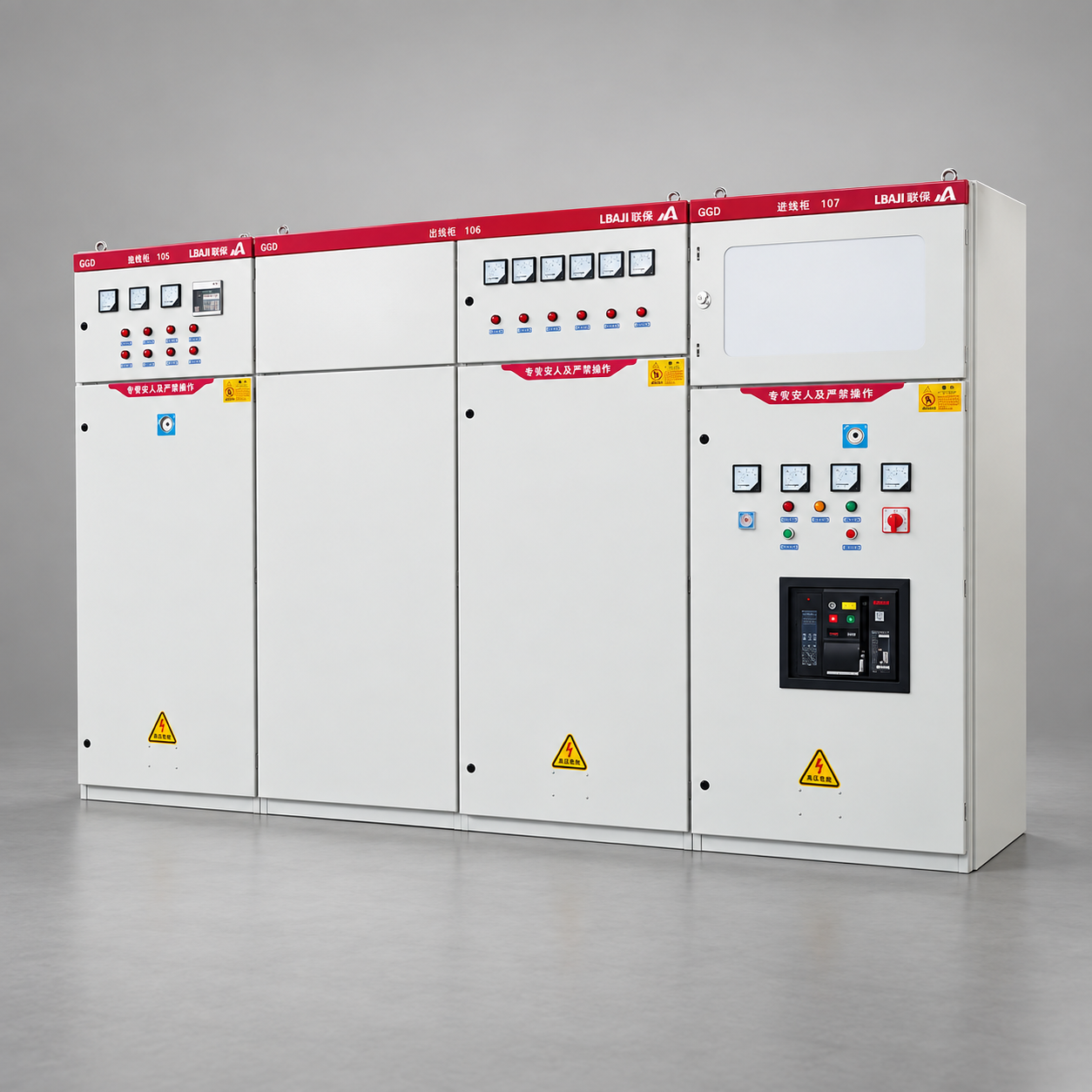
A switchgear lineup is usually divided into functional positions: incomer, bus coupler, metering, transformer supply and outgoing feeder, for example. Each position can have different circuit-breaker, CT, relay, cable-termination and interlocking requirements. Calling every cubicle “switchgear” without its feeder role obscures the protection boundary. A feeder trip affects the loads downstream of that circuit; a bus or transformer fault may affect more. The coordination study should show which device clears a fault first and where backup protection takes over.
A LBAJI XGW-12/630-25 ring main unit is a different type of distribution assembly from an indoor withdrawable metal-clad lineup. In a ring network, one enclosure may connect several medium-voltage cable ways and a transformer supply. Never infer the switch function of a visible compartment solely from an image. Check the actual circuit diagram and the ordered switching and protection functions.
Feeder sizing is more than a current figure
Design begins with the expected load, diversity, growth allowance and source conditions. A conductor must meet the applicable ampacity and installation rules after temperature, grouping, insulation and other relevant corrections. Voltage drop and motor starting can influence a long low-voltage feeder. Available short-circuit current affects conductor withstand and the interrupting ratings of protective equipment. Earthing, neutral treatment and cable routing matter as much as the nominal voltage. The installed circuit and its equipment must be evaluated as a system rather than selected from a single amperage figure.
For utility feeders, load distribution along the line, voltage regulation, sectionalizing, reconnection and contingency capacity also shape the design. A feeder serving many transformers can experience different loading and fault conditions at different points. A route that includes underground cable and overhead segments may require different protection and maintenance access. The U.S. Department of Energy distribution reliability report illustrates primary feeders, laterals, sectionalizing switches and line transformers in its network examples. It is background context, not a project design standard.
For a three-phase example, apparent power is approximately √3 × line-to-line voltage × line current under balanced conditions. That relation is useful for an initial load check, but it is not a complete feeder-sizing method. Power factor, harmonics, starting duty, protective-device settings and applicable code factors may alter the design. A 400 A feeder does not automatically need a “400 A cable”; installation conditions and the required protective relationship determine a compliant conductor selection.
Protection, selectivity and feeder boundaries
At minimum, the feeder’s protective design has to recognize overload and fault conditions appropriate to the circuit. Depending on voltage and application, it may also involve earth-fault, directional, differential, distance or voltage functions. Time-current coordination seeks to disconnect the smallest practical part of the system for a fault while leaving healthy areas energized. That goal must be balanced with equipment protection and safety. Setting a downstream breaker too slow merely to preserve continuity is not acceptable.
The project engineer should document the protective device at each feeder source, CT ratio and location, relay settings, downstream protection, fault-current study and the intended switching sequence. The protection boundary may not coincide with a physical cabinet boundary. If alternate generation or a photovoltaic source can feed the circuit, the study must include those sources and operating modes. Our protection relay guide explains relay roles, while the switchgear fundamentals guide covers the assembly context.
What a good feeder schedule records
A feeder schedule links a circuit ID to its origin and destination, voltage, phase arrangement, load basis, protective device, conductor or busway, length, route, grounding and drawing references. For a medium-voltage feeder, record cable type, termination design, switching/protection functions, CT and VT details, and any remote-control points. For a low-voltage feeder, list the panel or switchboard at each end, breaker frame and trip settings, cable arrangement, neutral and earth information, and the available fault rating. Keep the revision synchronized with the single-line diagram and the installed labels.
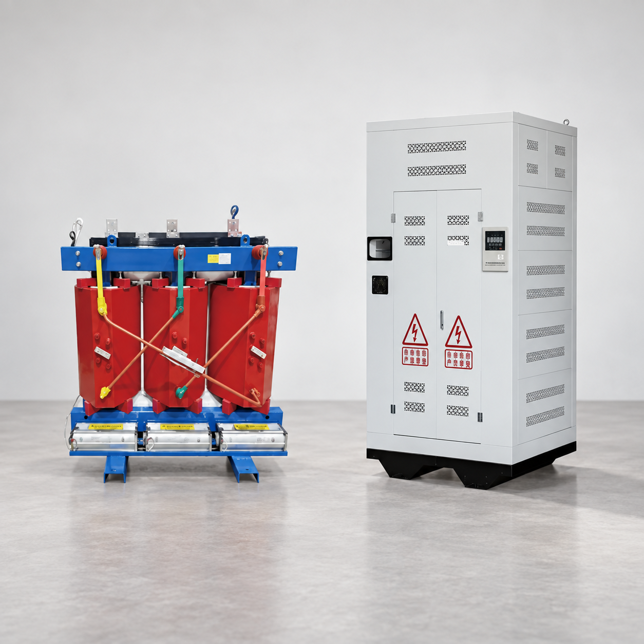
Equipment photographs should supplement, not replace, these records. The LBAJI SC(B) resin-insulation dry transformer may sit between a medium-voltage feeder and low-voltage distribution in one project. The pictured transformer and protective cabinet are reference products; the exact feeder terminations, voltage and capacity must come from the approved transformer and switchgear drawings.
Common feeder mistakes in procurement and operation
One common mistake is treating “feeder” as the name of a product rather than a circuit function. A quotation for a feeder panel is incomplete without its source, destination, protection, load and physical interfaces. Another mistake is copying a prior project’s breaker setting into a new network. Different source fault levels and downstream devices can change the appropriate setting. A third is assuming that an open switch means a feeder is safe to work on; backfeeds and stored energy can remain. Qualified personnel need the approved isolation, verification and earthing procedure for the actual site.
Finally, labels must remain accurate after changes. A circuit called “Feeder 4” in the control room, “F04” at a breaker and “RMU B” on a cable tag needs a documented mapping. Without it, maintenance teams can isolate or test the wrong circuit. The simplest useful question when reviewing a feeder is: “From exactly which source device to exactly which destination device, under which operating modes?” If that cannot be answered from current records, resolve the documentation before changing protection or making an outage plan.
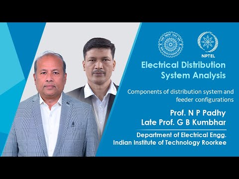
Further viewing: IIT Roorkee’s educational lecture introduces distribution-system components and feeder configurations. It does not replace a project switching or protection study.