Switchgear control voltage is the specified electrical supply used by auxiliary and control functions, such as operating coils, mechanisms, relays and indications. It is different from the main-circuit voltage carried by the switchgear. For procurement, identify each function, its required supply and the conditions at its terminals. Do not select a control voltage from the main voltage rating or a photograph of a control panel. The useful deliverable is an agreed auxiliary-supply schedule connected to the schematic, equipment data and project operating philosophy. That schedule should also explain what happens when a supply is lost and who is responsible for each interface.
Separate the main circuit from auxiliary functions
A medium-voltage assembly can include low-voltage auxiliary circuits whose purposes and supplies differ. Trip and close functions, protection electronics, communications, indications and other loads should be identified separately. One cabinet may therefore contain more than one relevant voltage and more than one source. A headline statement that simply says “control voltage” can leave important equipment interfaces unresolved.
Start with an auxiliary-load list linked to the schematic. For each item, record its function, supply type, rated value, manufacturer requirements and source. Do not assume that a relay’s power input and the contacts through which it commands another device share the same supply. A clear functional description prevents confusion between an electronic device supply, a control signal and an operating-coil circuit.
Decide AC or DC from the operating philosophy
The choice between AC and DC depends on the required function, available supply system, equipment options and the owner’s reliability requirements. An independently supported DC system can serve functions that must remain available when the normal AC source is absent, but its usefulness depends on the actual battery, charger, distribution and monitoring design. The label “DC control” alone proves none of those capabilities.
An AC arrangement also needs a documented assessment of its source and the consequences of loss. Some equipment can use different stored-energy or operating arrangements, so identify the proposed construction rather than forcing all designs into one assumption. The electrical designer and manufacturer should agree how each required action is supported in the credible operating states of the installation.

Read device requirements at the right terminals
Rated supply voltage is only part of the device information. The manufacturer’s permissible operating range, frequency where applicable, power demand and duty requirements also matter. Obtain the data for the actual ordered device variant. Two physically similar coils or mechanisms can have different electrical requirements, making appearance an unreliable way to select spares or approve substitutions.
Review the voltage at the relevant equipment terminals under the specified operating condition, not only at the source panel. Contacts, protective devices, connectors and conductors lie between those points. The resulting assessment must consider the complete circuit and its operating demand. Do not apply an arbitrary percentage window to every device; the applicable product requirements and supplied manufacturer data establish the criteria.
Account for transient demand and simultaneous actions
Auxiliary loads do not all behave like steady lighting loads. A mechanism or operating coil may impose a short-duration demand that differs from its steady condition. Request the supplier’s load information in a form the auxiliary-system designer can use. Include operating duration, duty limitations and any restrictions on repeated operations where the manufacturer specifies them.
The owner should identify which actions are credibly simultaneous and which are controlled by the operating philosophy. This provides a sound basis for evaluating source capacity and distribution. Avoid sizing a supply by adding convenient catalogue wattages without understanding the actual functions. Equally, do not assume that diversity eliminates a required simultaneous operation. Keep the agreed assumptions with the equipment schedule for later maintenance and expansion work.
Create an auxiliary-supply interface matrix
The matrix below is an original qualitative procurement checklist. It organizes responsibilities and evidence without prescribing a universal circuit design or safe work procedure. Each project should add its own identifiers and acceptance criteria, reviewed by the responsible electrical engineer and manufacturer.
Kontekst referensi: IEC 62271-1:2017 with Amendment 1:2021 common specifications scope. Daftar periksa kualitatif asli ini mengorganisir keputusan proyek; ini bukan standar yang direproduksi atau pengganti dari kriteria yang telah disetujui.
| Function or interface | Information to request | Acceptance question |
|---|---|---|
| Trip and close functions | Actual device variant, supply requirements and operating duty | Can each required action be supported in the specified operating states? |
| Protection and control electronics | Supply range, demand and behavior on loss or restoration | Will essential protection and indications behave as the owner requires? |
| Auxiliary distribution | Sources, circuit allocation, protective devices and identifiers | Are responsibilities and affected functions clear for each supply failure? |
| Remote interfaces | Signal type, contact duties and interface drawings | Do the switchgear and external systems agree electrically and functionally? |
| Pemantauan | Defined alarms, destinations and response ownership | Will a supply problem be detected and acted on? |
| Verification and handover | Approved checks, final drawings and settings records | Can the delivered arrangement be identified and maintained correctly? |
Evaluate voltage drop for the actual circuit
Circuit resistance can reduce the voltage available at a load while it operates. Assess the path using the project’s conductor lengths and sizes, terminal and contact arrangements, source condition and device demand. For a simple steady DC approximation, voltage drop equals current multiplied by total circuit resistance. This arithmetic relationship alone is not a complete operating-coil or battery-system design method.
For example, a hypothetical 2 ampere current through a 1 ohm complete path produces a 2 volt drop. Those numbers are purely illustrative and specify neither a real coil nor an acceptable margin. Dynamic behavior, contact performance and source variation may require a more detailed assessment. The designer must compare the resulting terminal conditions with the actual equipment requirements and retain the supporting assumptions.
Define what supply loss means for the installation
Ask what becomes unavailable when each auxiliary source or branch circuit is lost. The answer can involve protection availability, remote control, mechanism operation, indications or communications, depending on the design. Document the intended response and the operating restriction that applies. A shared supply can create common consequences even when the main power circuits remain energized.
The project should also define restoration behavior. Automatic recovery of an electronic supply does not necessarily mean that all operating functions should resume without review. Identify alarms, required checks and any relevant owner-approved operating controls. Do not invent a universal fail-safe state for all switchgear; the correct behavior depends on the equipment construction, protection philosophy and application.
Coordinate remote commands and dry contacts
Remote systems may provide contacts, digital communications or other defined interfaces. A contact that changes state does not by itself establish the voltage and current it is suitable to switch. Agree the signal source, receiving circuit, contact duty and isolation requirements through the interface documentation. Confirm which party supplies the voltage and which party owns the protective device and cable.
This is particularly important when a building management system, plant control system or substation control system connects to the switchgear. A functional request such as “remote open” should be translated into an approved interface description by the responsible designers. Keep communications commands distinct from hardwired operating circuits and from safety-related isolation. An interface table cannot replace an approved schematic and verification plan.

Keep unrelated auxiliary loads visible
Heaters, fans, lighting and service outlets may use supplies with different availability and isolation requirements from protection or operating circuits. Identify these loads instead of hiding them under one control-power total. Their loss may have a different immediate effect, but environmental control can still matter to the assembly’s long-term service conditions and maintenance responsibilities.
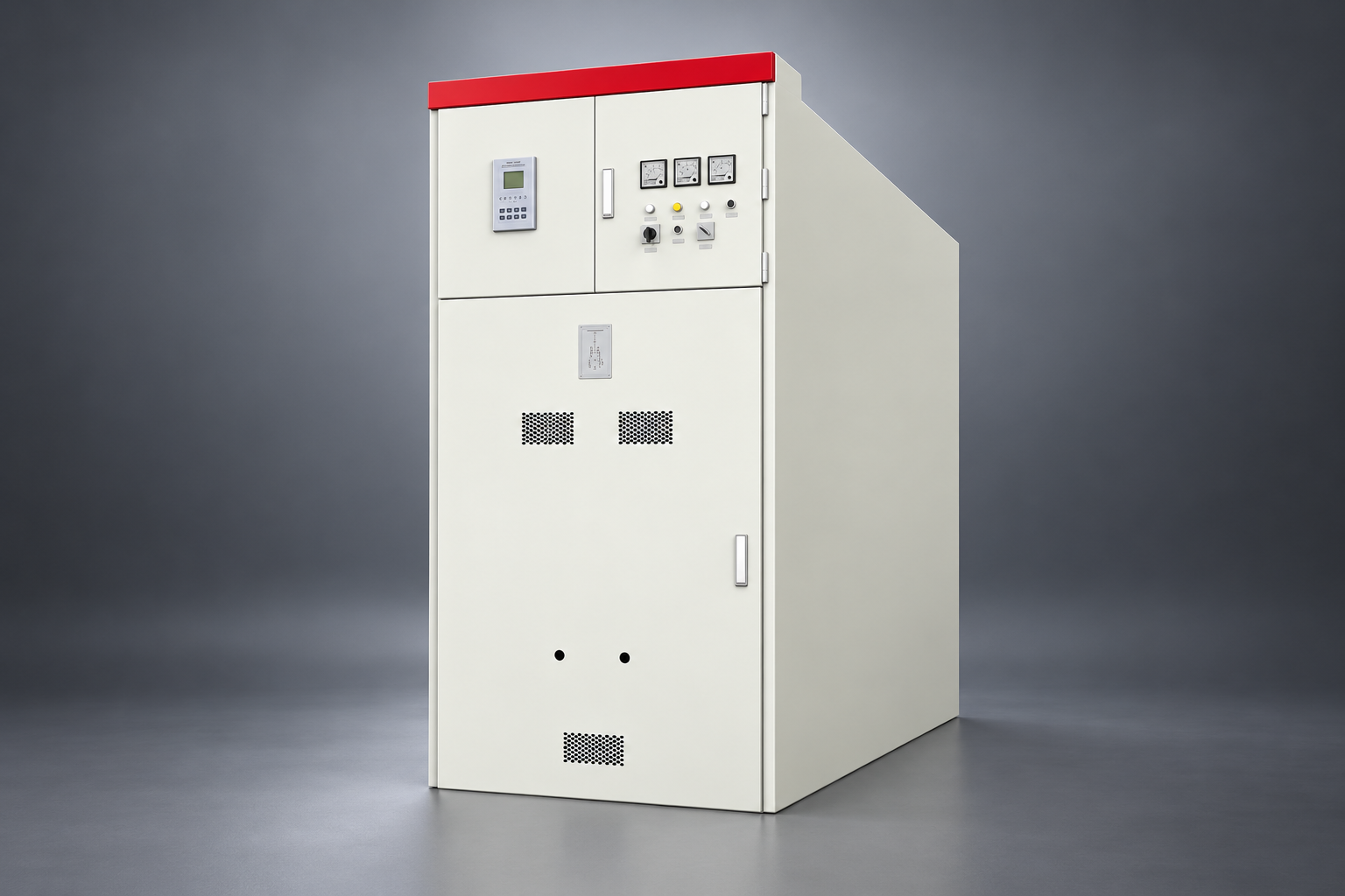
The cabinet’s exterior cannot reveal the actual auxiliary arrangement. For the KYN61 family illustrated here, obtain the ordered configuration’s schematic and device data rather than inferring a heater, battery or control transformer from a generated image. The illustrations are for equipment identification only. The supplier’s current offer must confirm which components and functions are included and which interfaces remain the site contractor’s responsibility.
Plan verification around the approved design
Verification should confirm the actual device variants, supply identification, circuit relationships and intended behavior through an approved inspection and test plan. Determine which checks can be performed in the factory and which require completed site interfaces. Record responsibilities, prerequisites, acceptance criteria and how deviations will be resolved before energization or operational handover.
Electrical testing and operating checks must be performed by competent personnel using the applicable work procedures and manufacturer instructions. In the United States, 29 CFR 1910.333 provides relevant requirements for electrical work practices, subject to the workplace and task. This article does not authorize energized troubleshooting or give a switching sequence. Other jurisdictions and installations require their own applicable requirements and engineering review.
Control substitutions and spare-part identification
A replacement operating coil or electronic device needs the correct electrical variant as well as mechanical compatibility. Retain part numbers, device ratings, circuit identifiers and relevant firmware or configuration information where applicable. Procurement should require the supplier to identify substitutions and explain their effect on the auxiliary-load schedule and interface assessment before approval.
For spares, store the technical identification with the asset record so technicians do not depend on a faded label or memory of an earlier order. If a source, cable route or operating philosophy changes, revisit the assessment rather than treating control voltage as a permanent one-line property. Good records reduce the chance that an apparently minor replacement creates a wider functional problem.
Build a complete RFQ and handover package
State the available auxiliary sources, required operating states, essential functions and external interfaces. Request device-specific supply data, a load schedule, schematic drawings, source-loss behavior, monitoring details and the agreed verification scope. Identify unresolved choices clearly so bidders price the same responsibility boundary. Applicable IEC 62271 documents provide part of the technical framework for high-voltage AC switchgear; catalogue pages establish scope rather than proving an individual offer’s compliance.
At handover, retain the approved and as-built versions, accepted deviations and verification records. Link them to the actual equipment identifiers and responsible maintenance team. The practical result is a control-supply specification that can be checked and maintained. It avoids guessing from the main voltage rating and gives future extension or replacement work a reliable starting point.
Pertanyaan yang sering diajukan
Is switchgear control voltage the same as its main voltage rating?
No. The main rating concerns the power circuit, while control and auxiliary functions have their own supplies and device requirements. One assembly can contain several relevant supply voltages.
Should all switchgear use DC control power?
The choice depends on the equipment, available sources and required operating behavior. Evaluate the complete auxiliary system and credible supply-loss conditions rather than relying on the AC or DC label alone.
Where should operating voltage be assessed?
Assess the relevant device terminals under the specified operating demand and source conditions. The source-panel value alone does not account for the complete circuit path.
Can a dry contact directly operate any trip coil?
No. The interface must satisfy the actual electrical duty, circuit and device requirements. Agree the source, receiving circuit, contact capability and responsibilities through the approved design.
What should the buyer include in the RFQ?
Include available sources, essential functions, operating states, device-specific requirements, auxiliary loads, monitoring, remote interfaces, verification scope and the required as-built handover records.
Sumber teknis dan peralatan terkait
Halaman katalog standar menetapkan lingkup dokumen; kepatuhan dan penerimaan memerlukan dokumen lengkap yang relevan serta review teknik proyek.
- IEC 62271-1:2017 with Amendment 1:2021 common specifications scope
- IEC 62271-200 assembly scope
- UK HSE HSG85: Electricity at work, safe working practices
- LBAJI KYN61-40.5 Perlengkapan Baja Berbahan Logam AC yang Dapat Dilepas
- Dasar-dasar peralatan switchgear
- Verifikasi dan pengujian peralatan pemutus sirkuit
- Checklist pemeliharaan peralatan pemutus sirkuit
Pendidikan lanjutan: latar belakang teknis
Video pendidikan independen ini menjelaskan prinsip pengukuran atau latar belakang peralatan yang telah dibahas di atas. Video ini tidak menunjukkan prosedur kerja yang aman untuk pemasangan spesifik tersebut. Sumber: Gaurav J – TheElectricalGuy.
Saksikan Dasar-Dasar Perangkat Listrik: Panduan Lengkap untuk Pemula | TheElectricalGuy