Switchgear protection coordination is the engineering process of arranging protective devices so that faults are detected and cleared with an agreed balance between equipment protection, safety and continuity of supply. A coordination study links the system model, fault calculations, device characteristics and actual settings. Selecting relays or spacing time-current curves by eye does not complete that process.
For buyers, the practical task is to obtain a study and commissioning record that apply to the supplied lineup and its real operating cases. This guide explains those deliverables, their interfaces and common acceptance gaps. It does not provide relay settings or instructions for working on energized equipment; those decisions require qualified engineering and approved site procedures.
Define the coordination objective before studying curves
Identify which faults each protection function should detect, which device is intended to operate first and what backup action is required if primary protection fails. The objective must account for equipment damage limits, personnel risk and the facility’s continuity requirements. No generic time delay resolves every competing requirement.
Selective operation aims to limit the area disconnected for a fault, within the defined system and current range. It is not a blanket promise that only one breaker will open under all circumstances. Define the required level of selectivity and record any accepted limitations at the relevant locations.
Separate network protection objectives from operational convenience. Keeping an upstream supply energized may benefit production, but extending clearing time can affect equipment duty and incident energy. The responsible engineer should document the chosen balance and the applicable project requirements instead of treating continuity as the only acceptance criterion.
Build the study from a controlled system model
Start with an accurate single-line diagram and an equipment schedule. Relevant inputs include source data, transformer ratings and impedances, cable information, generator contributions, earthing arrangement, connected loads and operating configurations. Record which inputs are confirmed and which remain provisional.
Include the actual protective devices: manufacturer, model, available functions, current-transformer ratios, relevant instrument-transformer data and circuit-breaker operating characteristics. A relay family name is not a complete representation of the installed scheme. Firmware, options or curve definitions can affect how the final settings are implemented.
Make the model revision traceable to the project drawings and study report. When information changes, identify which calculations and settings are affected. A study performed on an early tender diagram should not be accepted as an as-built deliverable merely because the project name is correct.
Evaluate maximum and minimum fault cases
The maximum fault case helps establish equipment duty and the upper range over which devices must operate. A minimum fault case may expose sensitivity or backup-protection gaps. The relevant study cases depend on the network and protection scheme; one fault current at the main incomer rarely describes the entire installation.
Alternative supplies and coupler states can change fault contribution and direction. A generator-fed island may present a different protection problem from a utility-fed configuration. Define the permitted operating states and identify where different setting groups or additional functions are required by the approved design.
Keep fault calculation quantities consistent with the protection analysis. Do not substitute a convenient catalogue figure for a calculated current at the protection location. Where data are uncertain, state the assumption, its sensitivity and the action needed to replace it before final acceptance.
Read time-current curves within their limits
Time-current plots help compare overcurrent devices and equipment boundaries over a selected range. Review the current reference, voltage base, device tolerances, transformer ratios and relevant operating times. Curves drawn on inconsistent bases can look coordinated while representing different physical quantities.
The complete clearing behaviour matters. Relay operation, output circuitry, trip mechanism and circuit-breaker interruption contribute to the result. An intentional relay delay is not the entire clearing time. Use the appropriate manufacturer data and study method for the devices being assessed.
A plot also has limits. High-current device interactions, current-limiting behaviour and some schemes may require manufacturer selectivity information, tested combinations or analysis beyond simple visual curve separation. State the range and conditions for any selectivity claim rather than extending a plot-based conclusion indefinitely.
Keep protection functions and zones explicit
Phase overcurrent, earth-fault protection, differential protection and other functions serve different purposes. Their application depends on the network, earthing system, measurement arrangement and equipment. A generic phase-overcurrent curve does not establish that every earth fault will be detected and cleared as intended.
Identify the protected zone, measurement points and tripping boundary for each applicable scheme. Current-transformer polarity, ratio, location and performance are part of that interface. The study should connect the intended function to the actual drawings and devices rather than leaving those details for commissioning staff to infer.
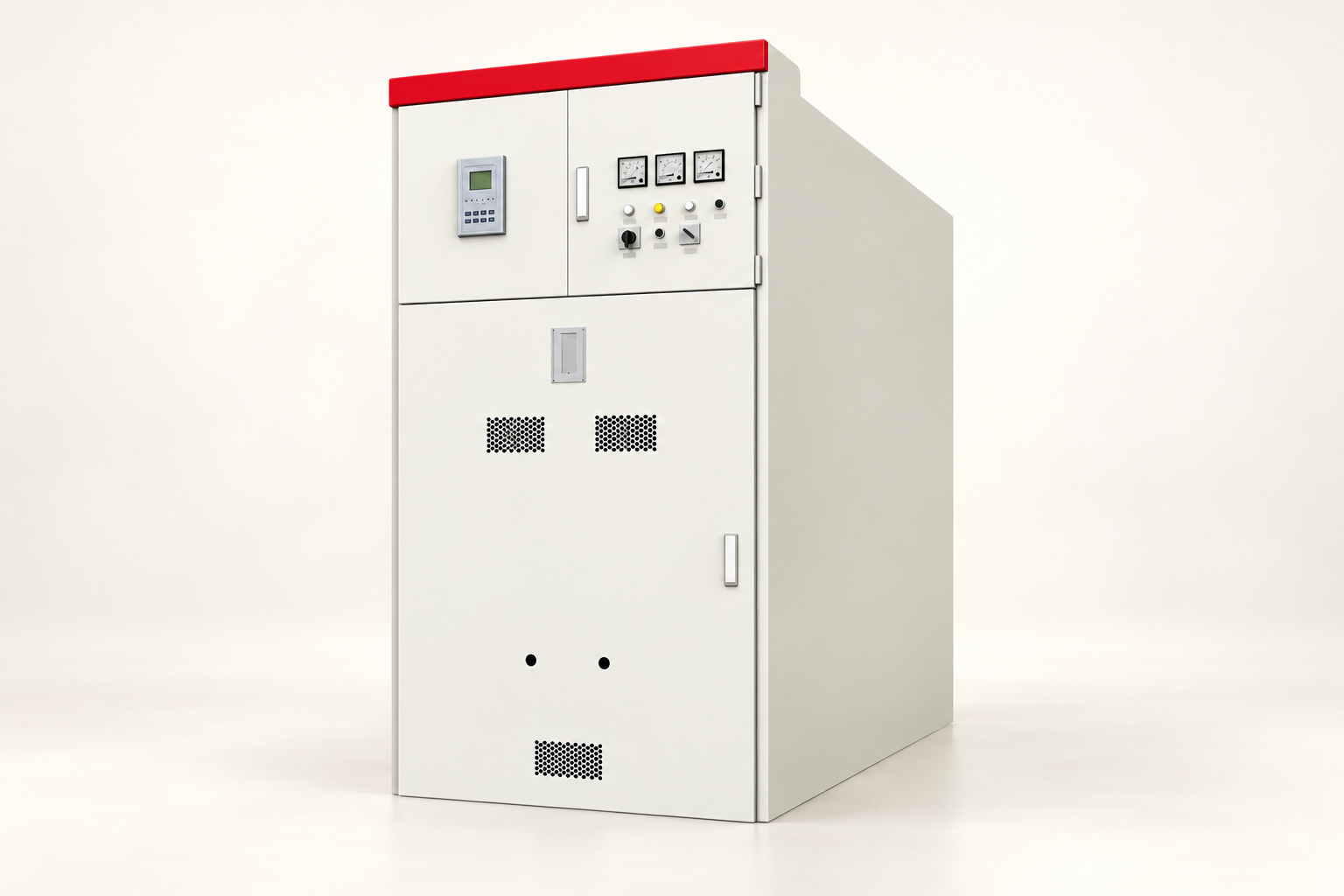
Intertripping, blocking, breaker-failure logic and setting-group selection introduce further interfaces where used. Record signal ownership, loss-of-signal behaviour and test requirements. These scheme functions should be designed and verified deliberately; they cannot be established from an exterior cabinet illustration.

Organize the acceptance documents
Kontekst referensi: IEEE educational presentation: Power System Protective Relays, Principles and Practices. Daftar periksa kualitatif asli ini mengorganisir keputusan proyek; ini bukan standar yang direproduksi atau pengganti dari kriteria yang telah disetujui.
| Deliverable | Essential content | Acceptance question |
|---|---|---|
| Design basis | Objectives, standards and permitted operating states | Are continuity and protection limits explicitly agreed? |
| System model | Confirmed inputs, assumptions and drawing revisions | Does it represent the supplied installation? |
| Fault analysis | Relevant maximum and minimum cases | Are duty and sensitivity conditions covered? |
| Coordination report | Devices, curves, functions and limitations | Are selectivity claims supported within their stated range? |
| Setting schedule | Approved device-specific values and revision | Can each installed relay be matched to its approved record? |
| Commissioning evidence | Implemented settings and functional test results | Does the installed scheme perform the approved design? |
Use this table to allocate deliverables between the system designer, switchgear supplier, protection engineer and commissioning contractor. Responsibility can be split contractually, but the technical interfaces still need an owner. A missing input is not resolved because it falls outside one supplier’s scope.
Balance selectivity with equipment and safety constraints
Delayed backup operation must remain compatible with the withstand and damage limits of the affected equipment. Review conductors, transformers, switchgear and other relevant components using the approved study basis. A coordination objective cannot justify exceeding a declared equipment duty.
Arc-flash assessment and protection coordination are related, but they are distinct tasks. A change in clearing time may affect incident energy. Any maintenance mode or alternative setting arrangement must have a defined purpose, operating procedure and engineering assessment rather than being treated as a universal cure.
Avoid introducing numerical coordination margins without a supported basis. Appropriate allowances depend on the devices, tolerances, breaker times and governing method. The study author should state the basis used and identify where the required separation or selectivity cannot be achieved.
Example of an operating-case gap
Consider a facility normally supplied by a utility transformer with a normally open coupler. The delivered report reviews that configuration, but the operating procedure also permits generator supply through a transfer arrangement. The protection review is incomplete until the permitted alternative case has been assessed.
The missing case may change current magnitude, direction or sensitivity. The solution could involve a revised scheme, different approved settings, operating restrictions or other engineered changes. It should not be guessed by reducing a pickup value without assessing load conditions and equipment protection.
A clear resolution record identifies the changed model, revised calculations, approved settings and required tests. It also states whether existing reports remain valid for other operating cases. This makes the decision usable for operations personnel and future project changes.

Verify the installed settings and scheme
The commissioning team should work from an approved setting schedule and controlled drawings. Record device identity and the values actually loaded, with appropriate version and revision information. A signed study is not evidence that every installed relay contains the intended configuration.
Testing should address the applicable measurement and trip paths, logic, interfaces and operating modes under the approved commissioning plan. The exact test method belongs to qualified specialists and the equipment instructions. Software simulation alone does not verify every field connection or breaker action.
Resolve discrepancies before the affected system is released. Preserve test records, approved deviations and final settings in the handover package. If a temporary setting is authorized, its purpose, owner and removal condition should be explicit so that it does not quietly become the permanent operating state.
Specify coordination scope in the purchase order
State whether the supplier must provide device data only, a complete study, an engineering review of another party’s study or commissioning support. Include required formats, input deadlines, drawing references and approval stages. An undefined request to provide coordinated protection is difficult to price and difficult to accept.
Ask for selectivity limitations and assumptions to be listed clearly. If device combinations require manufacturer evidence, identify who obtains it. Where the study relies on utility information, assign the request and confirmation process so that provisional source data do not survive unnoticed into final acceptance.
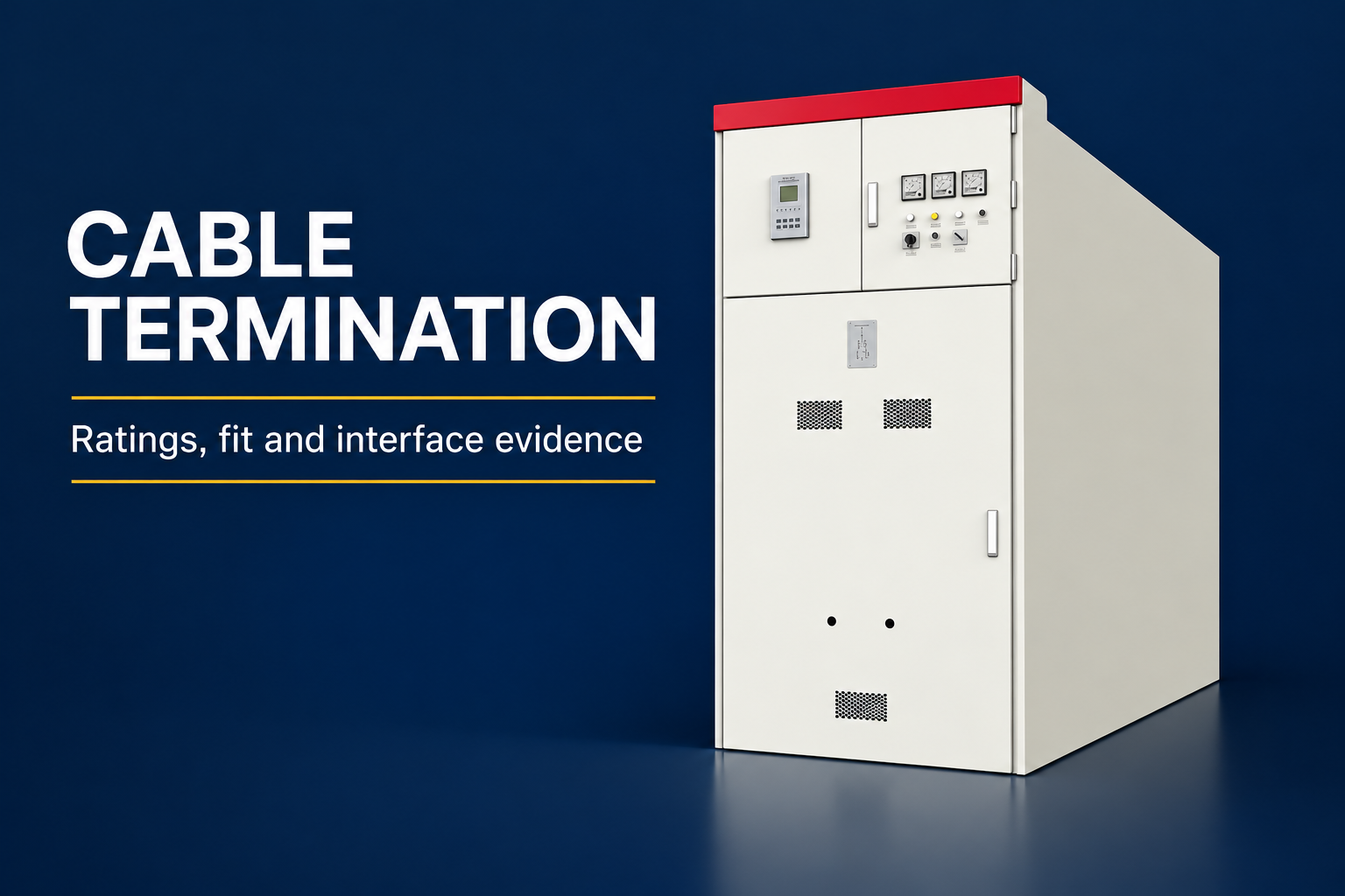
For an LBAJI switchgear enquiry, provide the system diagram and the required protection interfaces alongside the assembly specification. The KYN61 exterior shown here is a product-family reference, not proof of a particular installed relay or protection function. Confirm the offered equipment and scheme through project-specific documents.
Maintain coordination after handover
Update the assessment when sources, cables, transformers, loads, permitted operating states or protective devices change in a way that affects the study. A replacement relay with similar headline functions may implement characteristics differently. Review the substitution and its final settings rather than copying values without verification.
Keep the accepted study, device data, settings, test evidence and operating restrictions together. Make revision ownership clear. Protection coordination remains useful only while the record matches the installation and the permitted ways it operates.
Pertanyaan yang sering diajukan
Is a time-current curve plot a complete protection coordination study?
No. A complete review also needs a controlled system model, relevant operating cases, device data, applicable protection functions, equipment limits, assumptions and documented conclusions.
Why must minimum fault current be considered?
Lower fault levels can reveal detection or backup-protection gaps. The responsible engineer should assess the relevant cases rather than considering only maximum equipment duty.
Does selective operation always mean only the nearest breaker opens?
Selectivity claims have defined conditions and ranges. Backup operation, device interactions and scheme limitations must be included in the documented assessment.
Can a coordination delay be selected only to improve continuity?
No. The decision must also consider equipment withstand, protection requirements and safety implications. The engineering basis and accepted limitations should be recorded.
What proves that the delivered scheme matches the approved study?
Match installed device identities and actual settings to the approved schedule, then retain the required commissioning and functional test records for the applicable scheme and interfaces.
Sumber teknis dan peralatan terkait
Halaman katalog standar menetapkan lingkup dokumen; kepatuhan dan penerimaan memerlukan dokumen lengkap yang relevan serta review teknik proyek.
- IEEE educational presentation: Power System Protective Relays, Principles and Practices
- IEC 60909-0 short-circuit calculation scope
- UK HSE HSG85: Electricity at work, safe working practices
- LBAJI KYN61-40.5 Perlengkapan Baja Berbahan Logam AC yang Dapat Dilepas
- Dasar-dasar peralatan switchgear
- Verifikasi dan pengujian peralatan pemutus sirkuit
- Checklist pemeliharaan peralatan pemutus sirkuit
Pendidikan lanjutan: latar belakang teknis
Video pendidikan independen ini menjelaskan prinsip pengukuran atau latar belakang peralatan yang telah dibahas di atas. Video ini tidak menunjukkan prosedur kerja yang aman untuk pemasangan spesifik tersebut. Sumber: Gaurav J – TheElectricalGuy.
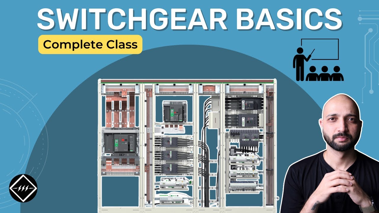
Saksikan Dasar-Dasar Perangkat Listrik: Panduan Lengkap untuk Pemula | TheElectricalGuy