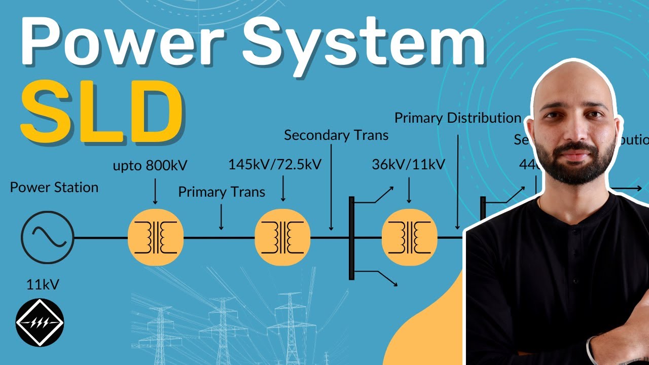
An 11kV switchgear single-line diagram is a functional map of a medium-voltage distribution system. One line represents a three-phase circuit, while symbols and labels identify incoming supplies, busbars, switching devices, instrument transformers, protection and outgoing feeders. It tells an engineer how power can flow and where it can be isolated; it is not a point-to-point wiring instruction or permission to operate equipment. This guide explains a practical way to read and review a typical 11kV arrangement without assuming that every site uses the same symbols or protection scheme.
What a one-line diagram does—and does not—show
A one-line compresses three-phase primary connections into a readable network view. It often omits physical cable routing, terminal numbers, panel internal wiring, control power circuits, phase-by-phase detail and mechanical clearances. Those belong in cable schedules, three-line drawings, elementary schematics, general-arrangement drawings and equipment manuals. An 11kV label normally describes the system’s nominal operating voltage; equipment selection also needs the specified highest voltage for equipment, insulation level, current and fault ratings. Never read a symbol alone as proof of a device’s actual capability.
The IEC 60617 graphical-symbol database is an authoritative symbol reference. A project’s drawing legend and applicable regional conventions still govern how its symbols are interpreted. The Schneider Electric medium-voltage technical guide gives broader equipment-selection context. Symbols can differ across drawing revisions, so obtain the approved as-built sheet rather than interpreting an unlabeled screenshot.
Read from the source toward the load
Begin at the utility or generator boundary. Find each incoming circuit, its nominal voltage, source identifier, metering point and primary switching device. Follow the line to the main bus. Then trace each outgoing feeder to its cable, transformer, motor or next distribution point. Mark every normally open point, bus tie, alternate source and potential backfeed. Finally, identify where current and voltage are measured, which relay commands each breaker, and what earthing or grounding facilities are represented. This source-to-load pass is much more reliable than memorizing isolated icons.
For a simple radial arrangement, the conceptual path may be: utility 11kV supply → incoming cable → incomer circuit breaker and CTs → 11kV bus → feeder breaker and CTs → outgoing cable → distribution transformer → low-voltage board. This is an explanatory sequence, not a construction drawing. A real scheme might have two incomers, an open bus section, an RMU in place of a breaker bay, or protection located elsewhere. Verify the approved arrangement before using it in any study or work permit.
| Drawing element | Question to ask | Document needed for confirmation |
|---|---|---|
| Incoming source | Which utility or generator supplies this bus? | Service agreement and source schedule |
| Breaker or load switch | Can it interrupt the expected load or fault duty? | Device nameplate, data sheet and protection study |
| Busbar and bus section | What operating configurations are possible? | Approved operating philosophy and interlock scheme |
| CT and VT | Which metering or protection element receives the signal? | Instrument-transformer schedule and secondary schematic |
| Outgoing feeder | What cable and downstream load does it serve? | Cable schedule and load list |
| Earthing switch | Which section can be earthed, and under what interlocks? | Panel manual and switching procedure |
Recognize the main switchgear functions
A circuit breaker can be commanded to interrupt fault current within its rated duty when paired with an appropriate protection system. A load-break switch has a different interruption duty; a disconnector provides an isolation function but is not necessarily designed to clear load or fault current. A fuse offers a specified fault-clearing function, often in a switch-fuse combination. An earthing switch is used under a prescribed switching and isolation sequence. A diagram that uses a generic switch icon without a device designation leaves important uncertainty—check the bill of materials and the installed unit.
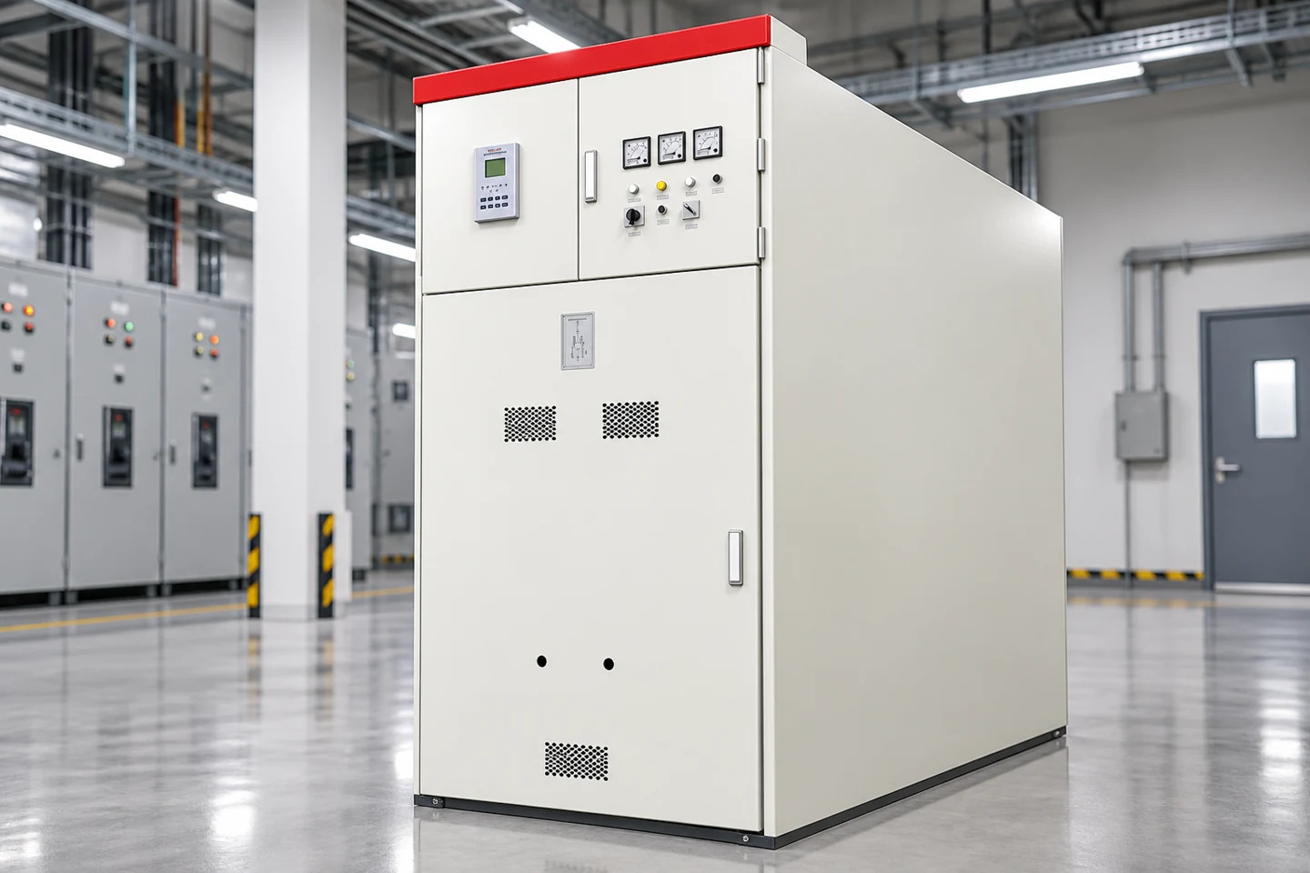
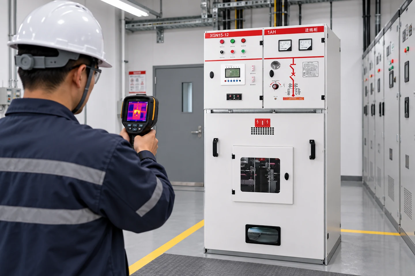
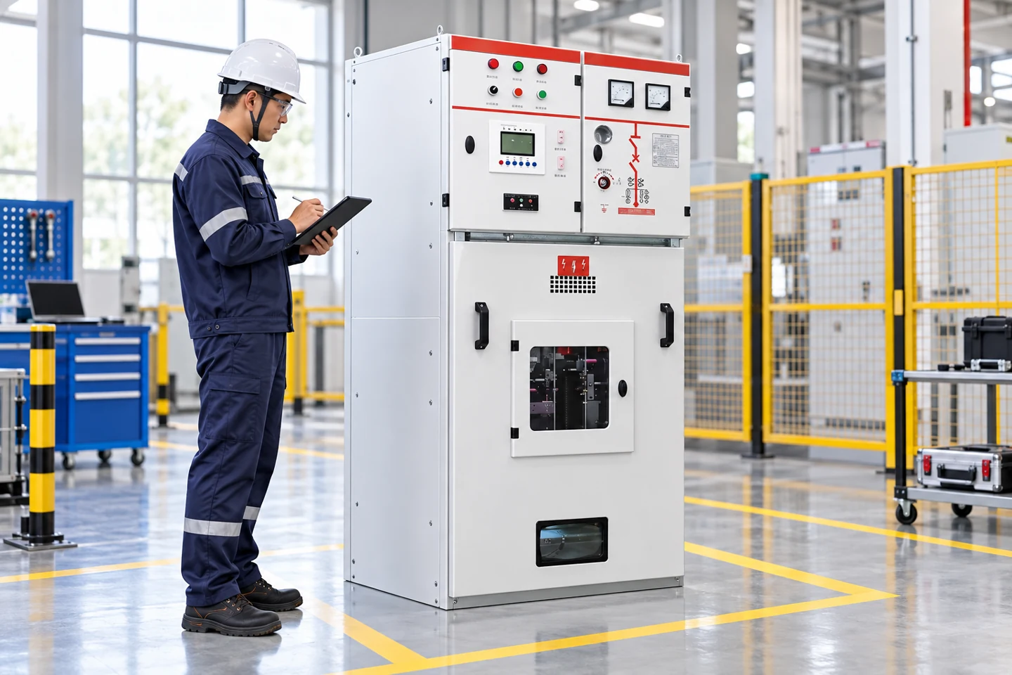
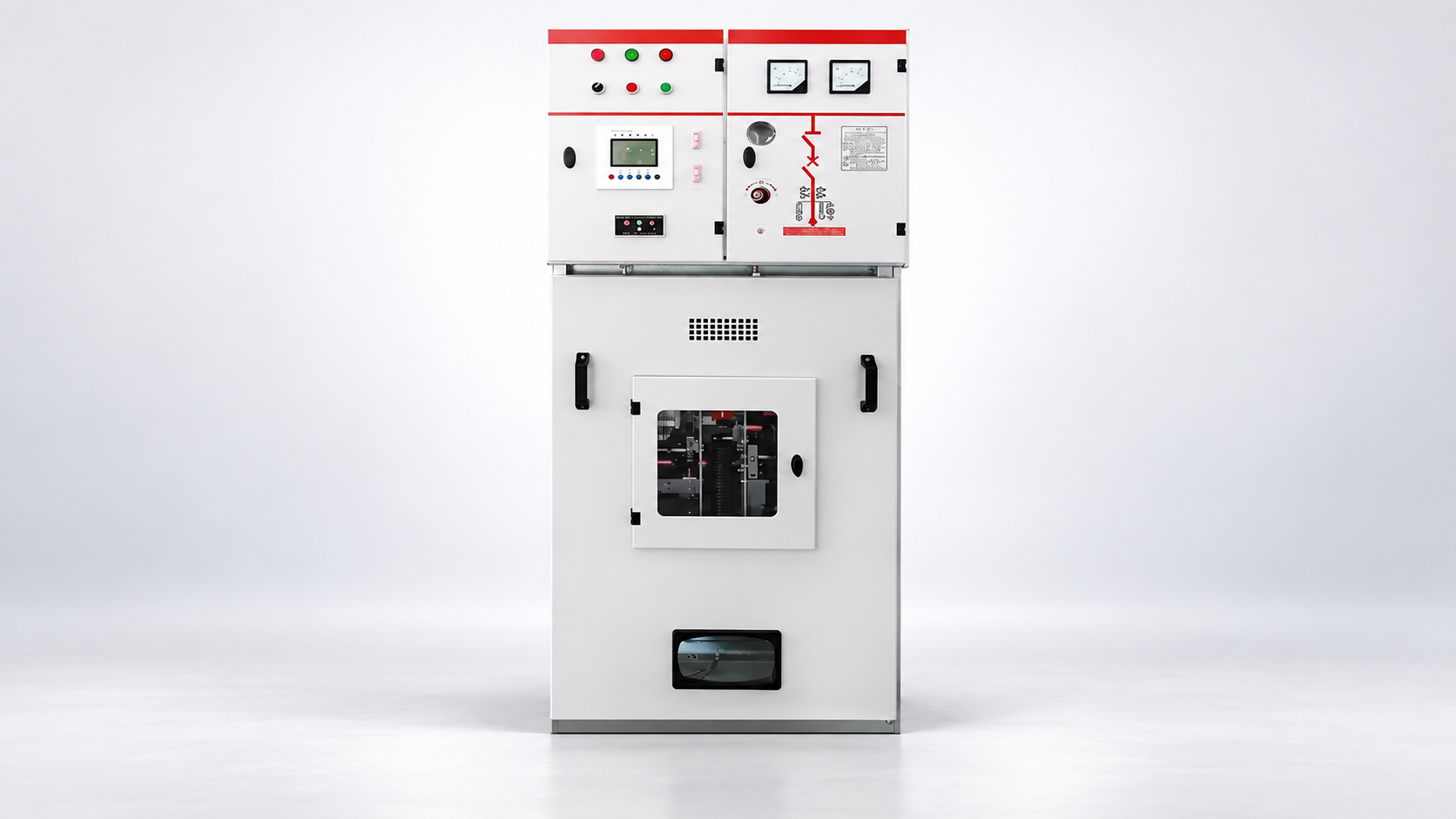
A medium-voltage lineup may use a withdrawable circuit-breaker bay such as the LBAJI KYN28A-12 cabinet. Its physical compartments and shutters are not fully described by the one-line. A compact ring main unit such as the LBAJI XGN15-12 may represent a different combination of ring switches, transformer protection and cable connections. Do not substitute one product image or symbol for the other’s exact internal scheme.
Understand bus sections, ties and alternate supplies
Two incoming feeders do not automatically mean the bus can be paralleled. A bus-section or bus-coupler device may normally be open, may close only after one incomer opens, or may be designed for synchronized parallel operation. The drawing should state normal positions, possible transfer modes and the boundaries of protection zones. If those notes are missing, ask for the operating philosophy and interlock logic. Assuming a closed tie can change fault levels and protective coordination substantially.
Trace a fault on each bus section: which breaker should trip, which healthy section stays energized, and whether an upstream device will back up a failed breaker. A one-line can identify likely zones but not prove relay settings or selectivity. Check the protection coordination study, CT ratios, relay settings and breaker-failure logic. Likewise, an alternate source on the page does not prove a transfer is automatic or that the source is available at the required capacity. The feeder overview explains the network role of these outgoing paths.
CTs, VTs and protection annotations
Current transformers (CTs) scale primary current for metering and relays; voltage transformers (VTs or PTs) provide scaled voltage signals. Their location on the one-line matters. A CT on the bus side of a breaker and one on the cable side can define different protection boundaries. Where differential protection is used, polarity and CT placement are critical, but they cannot be reconstructed safely from a low-resolution one-line alone. Read the instrument-transformer schedule and detailed secondary circuits.
Common relay numbers include 50 for instantaneous overcurrent, 51 for time overcurrent, 50N/51N for neutral or earth-fault functions, and 87 for differential protection. A number on a drawing indicates an intended function, not a guaranteed installed setting or a guarantee that the final trip circuit was proven. Scheme revisions, disabled elements and alternate setting groups matter. Check current approved settings and commissioning records. Our protection-relay guide
A VT symbol can support voltage metering, undervoltage logic, synchronization checks or directional protection, depending on its connections and relay configuration. Do not infer all those functions from the symbol alone. Likewise, a CT ratio printed on the diagram should be checked against the installed CT nameplate, selected tap and relay input configuration. An apparently minor mismatch can invalidate fault calculations or measurements.
Follow the transformer and low-voltage interface
An 11kV feeder often terminates at a distribution transformer and a low-voltage switchboard. The one-line should show transformer identifier, nominal voltages, rated power, connection group and grounding or earthing arrangement where needed for the study. Downstream low-voltage fault duty depends on transformer impedance and upstream contribution, not simply the transformer kVA. Protection at the 11kV side must coordinate with transformer inrush, thermal limits and downstream protection. These design choices require engineering calculations and manufacturer data.
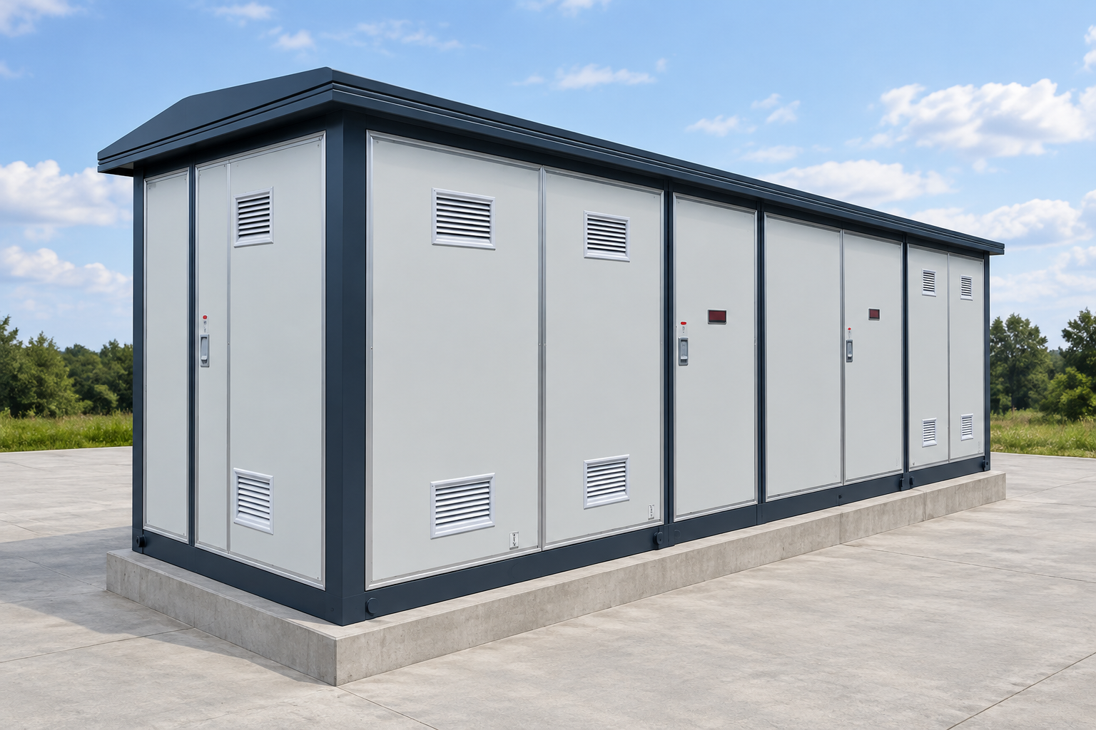
A packaged installation, such as the LBAJI YBM-12 prefabricated substation, combines several functions within one enclosure. The site one-line must still distinguish the MV compartment, transformer and LV distribution path. The photo below illustrates the exterior form only. A drawing for a particular purchased unit must match its approved internal configuration, actual terminal designations and utility interface.
Use the drawing to check ratings and boundaries
Before a switchgear specification is finalized, reconcile nominal system voltage with equipment rated voltage, power-frequency and impulse insulation levels, continuous current, short-time withstand, making current, breaking capacity and internal-arc classification where required. Confirm frequency, installation altitude, ambient limits, environmental conditions and cable termination interfaces. A notation such as “11kV, 630A” does not establish the complete rating set. The IEC 62271-200:2021 product-standard scope addresses AC metal-enclosed switchgear above 1kV up to and including 52kV; the applicable edition and product compliance evidence must be checked for the actual assembly.
Check fault current at every bus and feeder against the complete equipment duty, including the duration assumed for short-time withstand and the protection operating time. Revisit the values after adding a generator, changing transformer impedance or closing a bus tie. Ensure conductor and cable ratings correspond to their installation conditions. If an existing one-line lacks these values, record an open design question rather than filling the gap with a rating copied from another project.
Common reading errors and how to prevent them
The first error is treating a one-line as an as-built wiring diagram. It is a topological representation; control wiring, terminals and cable cores require their own drawings. The second is assuming all devices drawn in a normal-open state actually remain open in the field. Operating positions can change, and a static drawing may show normal rather than current status. The third is missing backfeed from a second utility, generator, PV inverter or downstream transformer. Isolation planning requires a current field check and authorized procedure, not just a line traced on paper.
Another common mistake is overlooking drawing revision and equipment identity. A replaced switchgear bay can retain a familiar label while its relay, CT ratio, breaker or cable termination changes. Compare drawing revision, asset tag, nameplate and commissioning file. Verify that upstream and downstream drawings connect at the same feeder and cable identifiers. Use a controlled redline and approval process for discrepancies; do not silently edit the one-line after work has been performed.
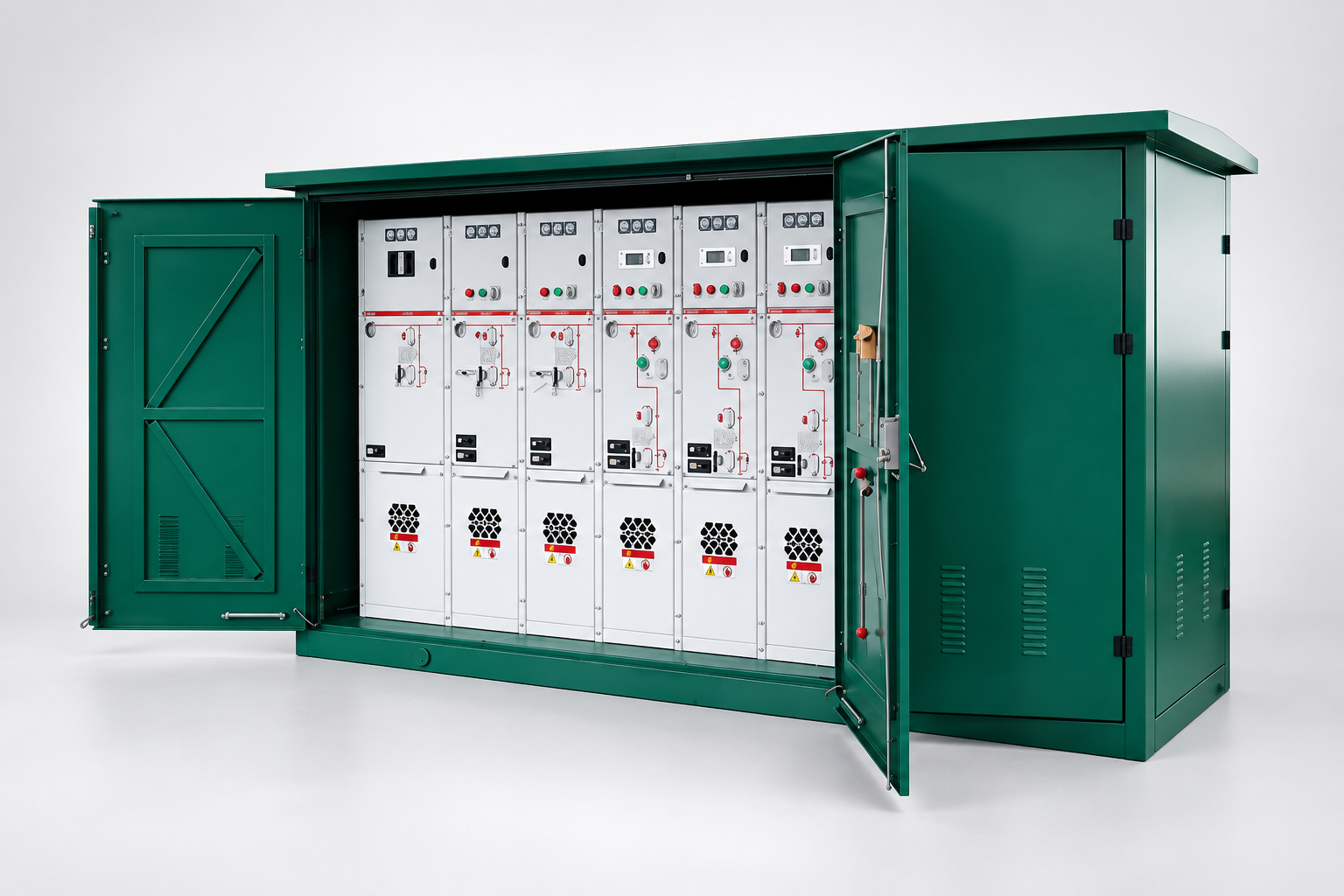
For ring networks, a compact outdoor enclosure such as the LBAJI XGW-12 unit can provide several bays, but bay count and functions are order-specific. Label each incoming ring leg, outgoing branch and normal-open point clearly. The same green enclosure can represent different circuit arrangements. A one-line must reflect the purchased configuration, not the appearance of a marketing photograph.
A practical review sequence for an 11kV drawing
First, confirm drawing number, revision, site boundary and the meaning of symbols in its legend. Second, trace every source to every load, marking normal and alternate paths. Third, list incomers, bus sections, outgoing feeders, CTs, VTs, protection zones and earthing points. Fourth, reconcile each tag with the equipment schedule, cable schedule and protection study. Fifth, check the exact product ratings and intended operating states. Sixth, resolve ambiguities with the designer or asset owner and issue a controlled updated drawing. A reviewer should be able to explain both the normal power path and what changes when a feeder, bus or source is isolated.
For construction and commissioning, add a field-verification step: compare the drawing with labels and nameplates, then confirm the breaker and interlock functions through approved tests. The Hướng dẫn kiểm tra thiết bị chuyển mạch
Further viewing: TheElectricalGuy’s educational explanation of a power-system single-line diagram illustrates how the simplified representation works; it is not a project-specific switching procedure.