A transformer bushing power factor test evaluates dielectric-loss behaviour under specified test conditions, usually alongside a capacitance measurement. The result helps assess insulation condition when compared with suitable factory or historical records. It does not measure the load power factor of the transformer. Interpretation depends on the bushing construction, measurement circuit, temperature and the quality of the comparison. Before reviewing a percentage, identify the actual bushing and confirm which insulation path was measured. A single result without those details cannot reliably establish condition or authorize continued service.
Start with bushing identity and construction
A bushing allows an energized conductor to pass through a grounded barrier while maintaining the required insulation. Its internal arrangement determines which tests are applicable. Some bushings have a capacitance-graded construction and an accessible test or potential tap; others do not. External colour, shape and a catalogue photograph do not establish the internal insulation technology or the availability of a tap.
Record the manufacturer, type, serial number and rated information from the actual equipment documentation. Identify whether the item has been replaced since the earlier baseline. A transformer serial number alone is not enough when an individual bushing may have changed. The correct comparison belongs to the identified component and its applicable test arrangement.
Power factor and dissipation factor describe related quantities
During an alternating-voltage insulation test, dielectric losses contribute a resistive component to the current. Power factor and dissipation factor express related aspects of that loss behaviour, but they are not identical definitions. Reports may use PF, DF or tan delta. Preserve the stated quantity, units and method rather than silently relabelling one as another.
A percentage and a decimal ratio also need clear labelling. Multiplying a ratio by one hundred expresses it as a percentage; it does not change the measured physical condition. When comparing reports, confirm that the apparent difference is not a difference in reporting format. The load power factor printed in an operating study is a separate subject and is not a bushing insulation result.
Why capacitance belongs beside the loss result
Capacitance provides additional information about the measured insulation system. A significant departure from a valid baseline can warrant investigation even when the loss result appears unremarkable. Conversely, an elevated loss result with little capacitance change still requires explanation. The two measurements should be reviewed together rather than using one favourable number to cancel the other.
The Bureau of Reclamation transformer manual describes bushing loss and capacitance testing as part of broader condition assessment. It is historical diagnostic background, not a universal acceptance table for every insulation technology. The applicable bushing documentation, complete method and asset history govern the actual assessment.
Understand what C1 and C2 refer to
For an applicable capacitance-graded bushing with a suitable tap, C1 commonly refers to the main insulation path between the central conductor and the tap. C2 concerns the path from the tap region toward the grounded flange and associated insulation. The actual construction and approved procedure determine how these measurements are made and interpreted.
Do not assume that every bushing supports both tests or that the permitted test conditions are the same for both paths. The tap arrangement can have specific limitations and restoration requirements. A report that says C1 or C2 without identifying the component, circuit and approved procedure is incomplete. This article does not provide a connection diagram or authorize access to a test tap.
Define the safety and equipment boundary
The work requires controlled isolation, verification, discharge and grounding arrangements appropriate to the installation. Competent personnel must follow the equipment-specific test procedure and site authorization. HSE HSG85 provides general safe-working guidance, but it does not replace those arrangements. Connected equipment and stored energy remain relevant even when the diagnostic objective is a small loss measurement.
The procedure should define which conductors and external circuits are included, excluded or guarded. It should also identify responsibility for restoring all test taps, covers and connections before service. A completed measurement is only one stage of the job; an incorrectly restored tap can introduce a separate equipment risk.
Conditions that affect a useful comparison
Record test temperature and the condition being represented, not just an unrelated weather reading. Where a correction is applied, identify the correction method and why it is appropriate to that bushing. A generic correction factor can create a false sense of comparability when the insulation technology or thermal condition differs.
Surface condition, moisture, nearby interference and measurement arrangement can also affect results. The report should document relevant observations and any approved cleaning or repeat measurement. Keep the initial result as well as the verified repeat. Deleting the first run removes context and makes it harder to understand why the final assessment changed.
A practical report-review table
This is a qualitative review table, not a list of numerical rejection limits. IEC 60137 defines a scope for insulated bushings and their characteristics and tests. A public scope page does not provide the complete field procedure or establish that a particular supplied bushing complies with every clause.
| Report field | Cần xác minh những gì | Why it changes interpretation |
|---|---|---|
| Bushing identity | Type, serial number and replacement history match the reference | A different component needs its own appropriate baseline |
| Measured insulation path | C1, C2 or other approved circuit is explicitly identified | Results from different circuits are not interchangeable |
| Reported loss quantity | PF, DF or tan delta and percent or ratio are clear | Labelling and unit differences can mimic deterioration |
| Capacitance | Value, units and suitable reference are present | Capacitance changes provide additional condition evidence |
| Temperature treatment | Measured condition and any correction are documented | Unsupported correction can distort a trend |
| Restoration and release | Tap and connection checks plus authorized disposition are recorded | A test result alone does not close the work safely |
How to review an unexpected increase
First confirm identity, circuit, units and comparable conditions. Check the original files rather than relying only on a transcribed summary. If the procedure permits a controlled repeat after addressing a documented measurement influence, retain the sequence and explain the change. A specialist should assess whether the remaining difference is significant for that construction and history.
An elevated result can be consistent with insulation deterioration or contamination, but it does not uniquely identify moisture or predict a failure date. Further investigation may include additional appropriate diagnostic methods and manufacturer consultation. State the evidence supporting the working explanation and what remains uncertain. Avoid turning a general internet threshold into a release rule.

What a stable result can and cannot establish
A stable result under comparable conditions is useful evidence. It does not independently establish the mechanical condition of the bushing, the integrity of every external connection or the condition of the transformer’s internal windings. External damage, leakage and abnormal operating observations still require assessment even when the reported dielectric loss remains similar to the baseline.
Likewise, a favourable test from several years ago does not resolve a new event. Use it as part of the history, then evaluate the current issue. Inspection and diagnostic intervals should reflect the owner’s maintenance strategy, equipment documentation and risk assessment. This article does not prescribe one calendar interval for all installations.
Example: two reports appear inconsistent
Consider a hypothetical maintenance review in which one report presents power factor in percent and another presents dissipation factor as a decimal. Before describing a rising trend, reconcile the quantity, reporting format, circuit and temperature treatment. If these differ, the reviewer should explain the comparison limitations and obtain clarification rather than joining the values into one chart.
Suppose the reconciled records still show a reproducible change alongside a capacitance discrepancy. That combination warrants a documented specialist assessment. The example intentionally supplies no fabricated measurements or pass limits. The useful lesson is to make the comparison valid before assigning a condition and to preserve both loss and capacitance evidence.
Ask for the right documentation during procurement
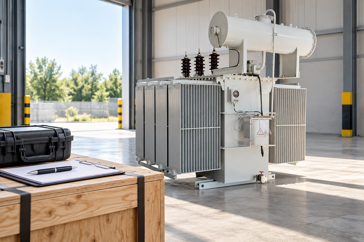
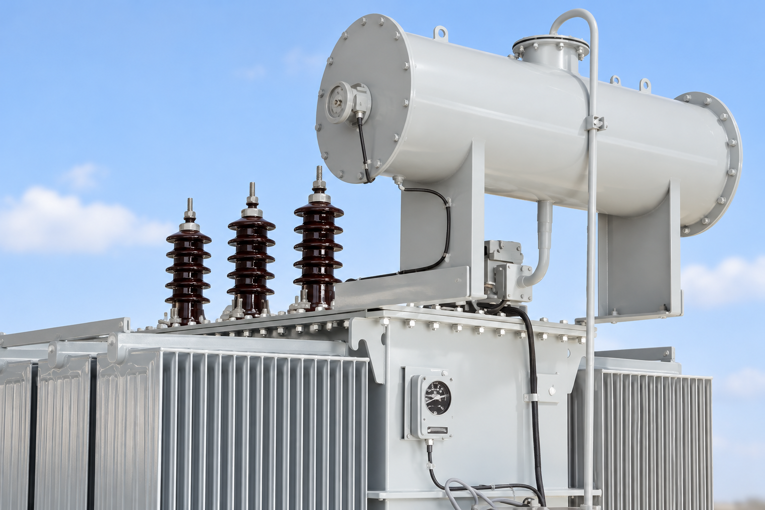
For an LBAJI 35kV oil-immersed transformer enquiry, request the actual bushing schedule, insulation technology, applicable test documentation and maintenance information. If a particular diagnostic provision is required, describe it in the specification and obtain confirmation of the proposed arrangement. Do not assume that the visible brown bushings in a reference image are capacitance-graded or have accessible test taps.
The enquiry should distinguish component factory records from transformer assembly testing and later site diagnostic work. Ask how individual bushing serial numbers are tied to the delivered transformer and which baseline data will be supplied. These are evidence requests, not claims that a catalogue product automatically includes a particular test service or certification.
Keep a usable component history
Store the report with original data, the component identity, relevant photographs, temperature records and the approved conclusion. Record replacements separately so future reviewers do not compare a new component with the old one’s trend. If instrument settings or analysis software change, retain enough detail to explain how comparisons were made.
The closing statement should identify the tested insulation path, the applicable criteria and the authorized disposition. List unresolved questions and follow-up actions clearly. An effective maintenance record lets the next engineer understand what the result means without reconstructing the test from memory or guessing which component was connected.
Avoid confusing bushing tests with oil specimen tests
An oil power-factor or dissipation-factor measurement examines a liquid sample in a laboratory cell under its own method and conditions. A bushing measurement examines a different insulation system and circuit. Their results cannot be exchanged merely because similar words appear in the report. The same distinction applies to the transformer’s overall insulation measurement.
Use each result for the question it actually addresses. If a broader assessment includes oil analysis, winding tests and bushing measurements, keep their baselines and criteria separately identified, then explain how they contribute to the equipment decision. This preserves useful connections between evidence without merging unlike measurements into one unsupported health score.
Các câu hỏi thường gặp
Is bushing power factor the same as transformer load power factor?
No. The bushing test concerns dielectric loss under specified diagnostic conditions, while load power factor describes an operating electrical relationship.
Can all bushings be tested as C1 and C2?
No. Applicable tests depend on construction, tap arrangement and the manufacturer’s procedure. Do not assume a suitable tap exists from the external appearance.
Does an elevated result prove moisture ingress?
No. Verify the measurement and consider the actual insulation system, conditions and complementary findings before assigning a cause.
Can a stable power-factor result override a capacitance change?
No. Review both measurements with suitable baselines and component documentation. An unexplained capacitance change still warrants technical assessment.
Related equipment and guides
- LBAJI 35kV oil-immersed power transformer
- Hướng dẫn toàn diện về các nguyên 2 lý cơ bản của Transformer
- Transformer Winding Resistance Test: Temperature, Tap Position and Report Review
- Transformer Turns Ratio Test: Nameplate, Tap Schedule and Result Review
Technical references
- Bureau of Reclamation: Transformers, Basics, Maintenance and Diagnostics (2005; historical diagnostic background)
- IEC 60137:2017 RLV: Insulated bushings for alternating voltages above 1000 V (published scope)
- HSE HSG85: Electricity at work, safe working practices
Further learning: Dielectric response concepts
This NPTEL university lecture introduces dielectric response in a polymers course. It supports the concept that insulation response depends on material and conditions; it is not a bushing test demonstration, a connection guide or a source of bushing acceptance limits. Source: NPTEL-NOC IITM.
Watch #41 Dielectric Response | Part I | Polymers Concepts, Properties, Uses & Sustainability