A shunt-trip circuit breaker has an accessory that opens the breaker when a separate control signal energizes its trip coil. The control circuit may be initiated by an emergency-stop system, fire alarm, remote trip pushbutton, protective relay or building-management system. There is no safe universal wiring diagram: the coil voltage, terminal designations, auxiliary contacts, control-source behavior and breaker model must be verified from the manufacturer’s instructions. This guide explains the functions and review steps without telling anyone to work on energized equipment.
Separate the breaker from the trip accessory
The breaker interrupts the protected power circuit. The shunt-trip accessory is a control input that causes the mechanism to open. It is not the same as an undervoltage release, which trips or prevents closing when its control supply is absent. A shunt trip may require a momentary pulse or a maintained signal depending on the accessory and control design. Identify the accessory part number and rated control voltage before drawing the circuit.
Read the breaker accessory diagram and nameplate. Some devices use dedicated coil terminals; others use a plug-in accessory block. A normally open initiating contact may close to energize the coil, while an auxiliary contact can report breaker position. Do not infer terminal numbers from another breaker family. The OSHA lockout/tagout requirements reinforce that a remote trip command is a control function, not proof of safe isolation.
| Design item | Question | Verification evidence |
|---|---|---|
| Shunt-trip coil | What control voltage, duty and terminals does it use? | Accessory data sheet and breaker wiring diagram |
| Initiating contact | What event closes or opens the trip command? | Cause-and-effect matrix and control schematic |
| Control power | Is the source AC or DC, fused and supervised? | Control-power drawing and protection schedule |
| Breaker feedback | How is open, closed or tripped status reported? | Auxiliary-contact schedule and PLC/fire-alarm I/O list |
| Reset and reclose | What prevents an unintended re-energization? | Operating philosophy and commissioning test |
Conceptual control path
A conceptual circuit has a control-power source, protective device, initiating contact, shunt-trip coil and return. The initiating device may be a pushbutton, relay output or safety controller. A local trip button may be wired in parallel with a remote trip contact, but the final arrangement depends on the required fail state and supervision. A maintained fire-alarm signal and a momentary emergency pushbutton are not interchangeable without a defined reset sequence.
Use the manufacturer’s diagram to identify polarity for DC coils and the correct neutral or return for AC coils. Protect the control circuit with a fuse or breaker suitable for the conductors and coil inrush. If the circuit is monitored, the supervision resistor or end-of-line device must be installed exactly as the life-safety or protection system requires. Never place a generic component into a safety circuit because its voltage rating appears similar.

Control voltage and transient protection
Confirm the coil’s nominal voltage, pickup range, release time, duty and allowable energization duration. An AC coil and DC coil may require different suppression and polarity treatment. A DC coil’s collapsing field can produce a transient that damages a PLC output or relay contact; the manufacturer’s permitted diode, varistor or RC suppressor must be used. A suppression device that is wrong for the circuit can slow operation or prevent the trip.
Size the control source for the coil and every simultaneously energized accessory. Check voltage at the coil during the trip command, including cable drop and the output device’s voltage loss. A power supply that is adequate at idle may sag during an alarm event. Record the control-source fuse, conductor size, terminal path and measured voltage in the commissioning file.
Interlocks, feedback and fail-safe behavior
Decide what happens if the initiating cable opens, control power fails, a relay sticks or the breaker is already open. A shunt trip normally acts only when its coil is energized, so it does not automatically provide the same fail-safe behavior as an undervoltage release. Life-safety and process-hazard studies determine whether the design should trip on a supervised fault, use redundant contacts or provide an independent release.
Use auxiliary contacts to distinguish a commanded trip from a breaker that opened because of an overcurrent trip, undervoltage release or mechanical problem. The feedback should be mapped to the correct PLC, fire panel or SCADA input and tested under each relevant condition. Do not use a single “not running” signal as proof that the breaker is isolated. A breaker can be open while cables or an alternate source remain energized.
Application examples
An emergency-stop circuit may send a controlled trip command to disconnect a machine supply. A fire-alarm interface may trip a feeder when a defined cause-and-effect matrix is active. A protective relay may issue a trip output after detecting a fault. Each application has different reset, supervision, redundancy and testing requirements. The control narrative should say whether the trip is momentary or maintained and what an operator must do before reclose.
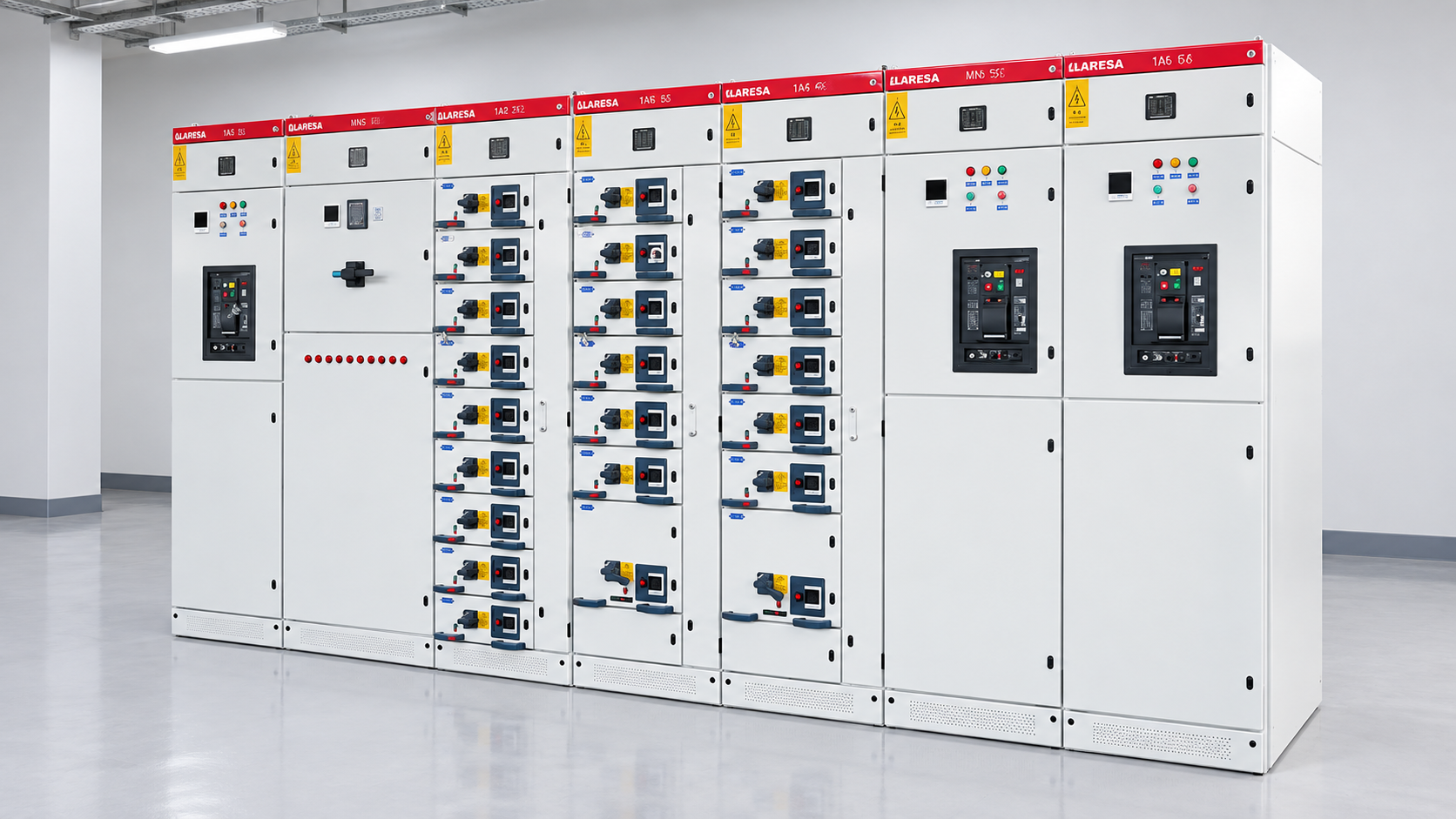
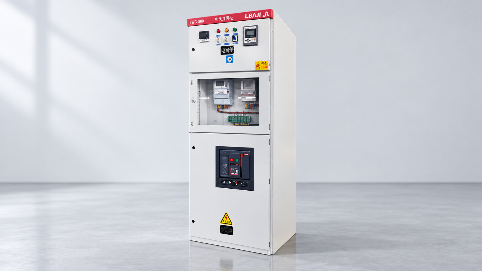
The LBAJI GGD low-voltage switchgear and MNS/GCK/GCS lineup are product references for low-voltage distribution architectures. Their external photographs do not reveal the installed breaker accessory, coil voltage or terminal arrangement. Request the exact ordered schematic before designing a shunt-trip interface.
Commissioning and documentation
Before testing, isolate the power circuit under an approved procedure and confirm the control-test boundaries. Verify accessory identity, coil voltage, terminal torque, fuse rating, conductor identification and protective-earth continuity. Test the initiating device, trip operation, breaker auxiliary contacts, alarm, reset, remote indication and loss-of-control-power response. Record the actual measured coil voltage and trip time where the manufacturer’s method calls for it.
Test nuisance-trip prevention as well as the trip itself. Check that a momentary command does not leave an unsafe automatic-reclose path and that a maintained alarm cannot be reset without the required authorization. Restore links, covers, settings and interlocks after the test. The switchgear testing guide explains why an accessory test is only one part of a complete acceptance program.
A final drawing package should include the breaker and accessory part numbers, control-voltage source, terminal numbers, initiating devices, suppression, feedback contacts, cause-and-effect reference, reset logic and test record. If the breaker is replaced, repeat the accessory compatibility review rather than transferring the old wire labels without checking.
Review the complete cause-and-effect chain
Trace the command from the initiating event to the final breaker contact. For a fire interface, identify the fire panel output, interface relay, supervised wiring, shunt-trip coil, breaker auxiliary feedback and alarm indication. For an emergency stop, identify every energy source that must stop, the reset location and the conditions for a controlled restart. For a relay trip, identify CT or sensor inputs, relay output contacts, trip-circuit supervision and breaker-failure backup. A command that opens one breaker may leave another source energized, so the single-line must be reviewed with the control schematic.
Check the behavior when wires are open or shorted, when the control supply is lost, when the breaker is already open and when an operator attempts to close it again. Some systems require a maintained trip signal until the initiating condition is cleared; others use a pulse and a mechanical reset. Do not invent a fail-safe response from a generic diagram. Record the approved behavior in the cause-and-effect matrix and test both expected and abnormal cases.
Remote-trip wiring also needs practical maintenance details. Provide a local test point or test procedure that does not expose workers to energized primary parts. Label control fuses and terminals, retain spare accessory information and note whether the breaker must be racked out or isolated for an accessory replacement. Keep the final schematic with the asset and update it after any breaker, relay, fire-panel or PLC change.
Do not confuse a trip command with isolation
A shunt-trip command opens the breaker mechanism; it does not prove that the line or load terminals are dead, that a second source is disconnected, or that stored energy has been released. The approved isolation procedure may require opening additional devices, testing for absence of voltage and applying earths. Remote status, a dark HMI or a breaker handle position is not a substitute for the specified verification method.
Review the single-line for transformers, generators, UPS systems, PV inverters, bus ties and control-power backfeeds. Decide which devices must trip together and which must remain available for safe control or emergency lighting. Document the boundary of the shunt-trip function and the devices that are outside it. This prevents a well-wired accessory from creating false confidence about the whole installation.
After commissioning, include the accessory in periodic inspection. Check control-fuse condition, terminal tightness, auxiliary-contact operation, trip indication, alarm history and the approved test interval. If the breaker, coil, fire panel, relay or PLC is replaced, repeat the compatibility and cause-and-effect review. Preserve the test result with the exact asset number and drawing revision so future maintenance does not rely on a generic diagram.
Further viewing: An educational circuit-breaker testing lesson can help explain trip circuits; the exact breaker manual and approved site procedure control the work.