An SF6 circuit breaker is a high-voltage switching device that uses sulfur hexafluoride gas for insulation and arc interruption. The gas has high dielectric strength and can capture free electrons, allowing a compact interrupter to withstand recovery voltage after current is cleared. SF6 equipment is engineered as a sealed, controlled system; it is not simply a conventional breaker filled with a different gas.
How the interrupter works
When the contacts separate, an arc forms. The breaker directs pressurized SF6 through the arc zone, cooling the plasma and reducing its conductivity near current zero. After interruption, the gas restores dielectric strength between the contacts. Puffer, self-blast and hybrid mechanisms use different combinations of contact movement and gas pressure. The exact design, rated voltage and interrupting duty come from the manufacturer’s type-test data.
SF6 also insulates live parts from the earthed enclosure. This enables compact gas-insulated switchgear and ring-main units in substations where space, pollution or weather exposure makes air insulation difficult. The gas compartment, density monitor, pressure relief path and cable terminations are part of the system and must be maintained together.
| Specification | Why it matters | Evidence |
|---|---|---|
| Rated voltage | Sets insulation and recovery-voltage duty | Type-test certificate and nameplate |
| Continuous current | Determines conductor and contact heating | Rated current and temperature-rise data |
| Short-circuit current | Determines arc-interruption capability | Fault study and breaker rating |
| Gas density | Low density can reduce insulation and interruption performance | Density monitor and alarm settings |
| Environmental declaration | Controls handling, recovery and reporting | Manufacturer procedure and local rules |
Where SF6 breakers are used
SF6 breakers are used in medium- and high-voltage substations, transmission switchyards, compact gas-insulated switchgear, ring-main units and industrial distribution systems. They are selected when high interrupting duty, compact dimensions and controlled insulation are important. New projects may also evaluate vacuum or alternative-gas technology, depending on voltage, duty, lifecycle and environmental requirements.
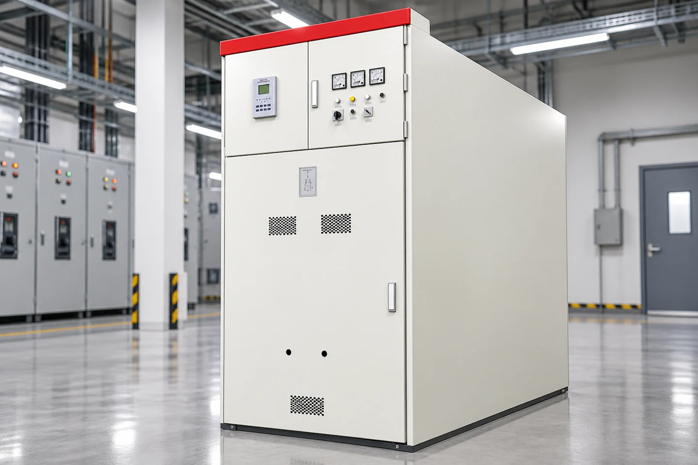
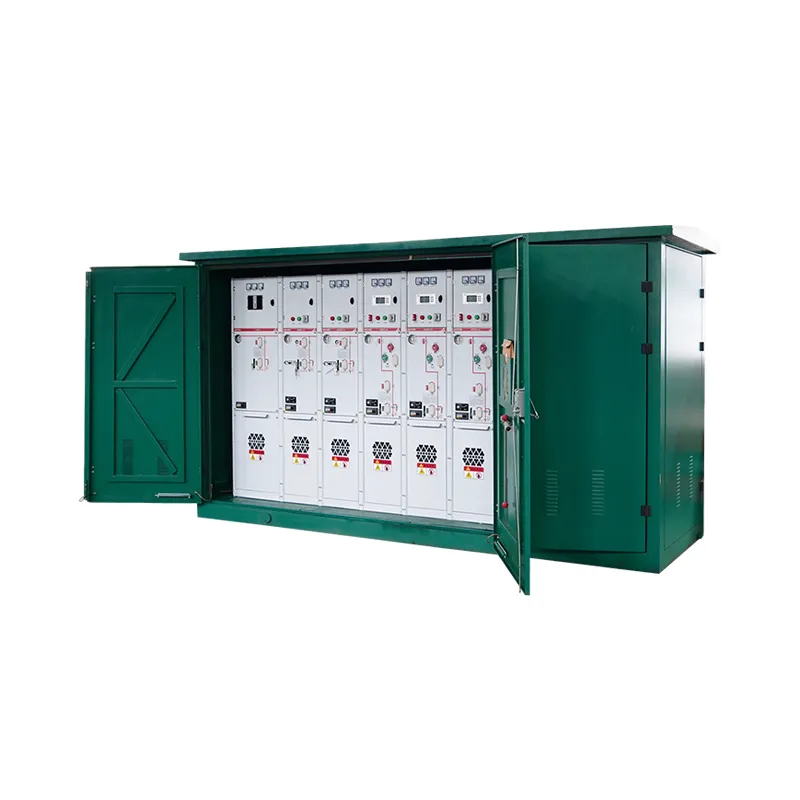
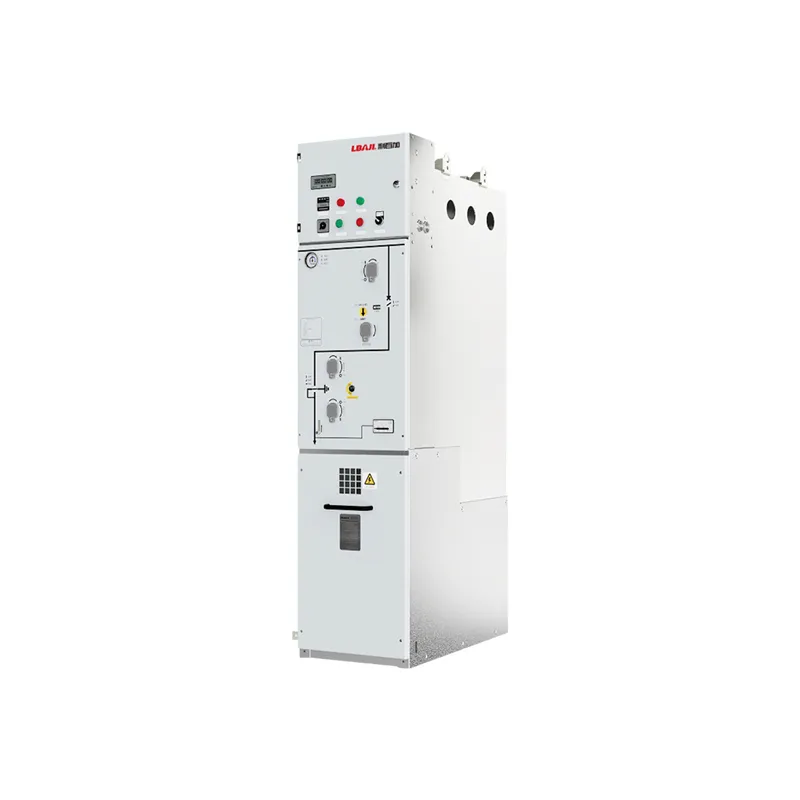
A gas-insulated ring-main unit can combine load switches, circuit breakers, earthing switches, busbars and cable compartments in a sealed tank. The external cabinet cannot reveal the internal gas pressure or switching arrangement. The LBAJI HC-40.5 ring-network switchgear is a product reference; the approved data sheet controls the actual gas system.
Ratings and coordination
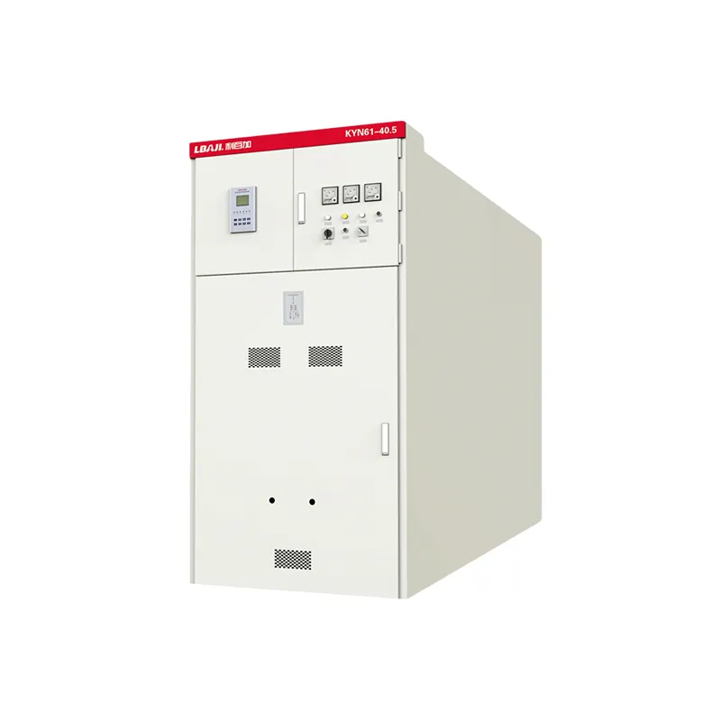
Specify rated voltage, highest system voltage, rated normal current, short-circuit breaking current, short-time withstand, peak withstand, power-frequency withstand, lightning impulse level, operating sequence and mechanical endurance. Confirm the breaker is suitable for the system frequency and grounding arrangement. A 12 kV ring-main unit and a 40.5 kV metal-enclosed assembly are different designs even when both use SF6.
Coordinate the breaker with protection relays, current transformers, voltage transformers, fuses and upstream sources. Review utility, transformer, generator, motor and alternate-feed contributions. Relay settings must clear faults within the breaker duty and cable thermal limits. Record the operating sequence, trip coil voltage and breaker-failure backup scheme.
Gas management and environmental control
SF6 is a potent greenhouse gas, so handling requires a controlled procedure. Do not vent gas during maintenance. Use approved recovery equipment, leak detection and recordkeeping. Follow the applicable local environmental regulations and the manufacturer’s instructions for filling, recovery, recycling and disposal. Personnel should be trained for the specific equipment and gas-handling method.
Density monitors often provide alarm and lockout thresholds. A low-density alarm may indicate leakage or temperature-related pressure change; it is not a reason to bypass the monitor. Investigate the cause, isolate the equipment as required and restore the specified density before service. Keep gas records, test results and leak repairs with the asset history.
Mechanical and control system
The operating mechanism may be spring, hydraulic or motor charged. Verify anti-pumping, trip-free operation, close and trip coil voltage, auxiliary contacts and local/remote selector logic. Earthing switches and cable-compartment interlocks prevent unsafe access. A key interlock or trapped-key system should be tested in every permitted operating sequence.
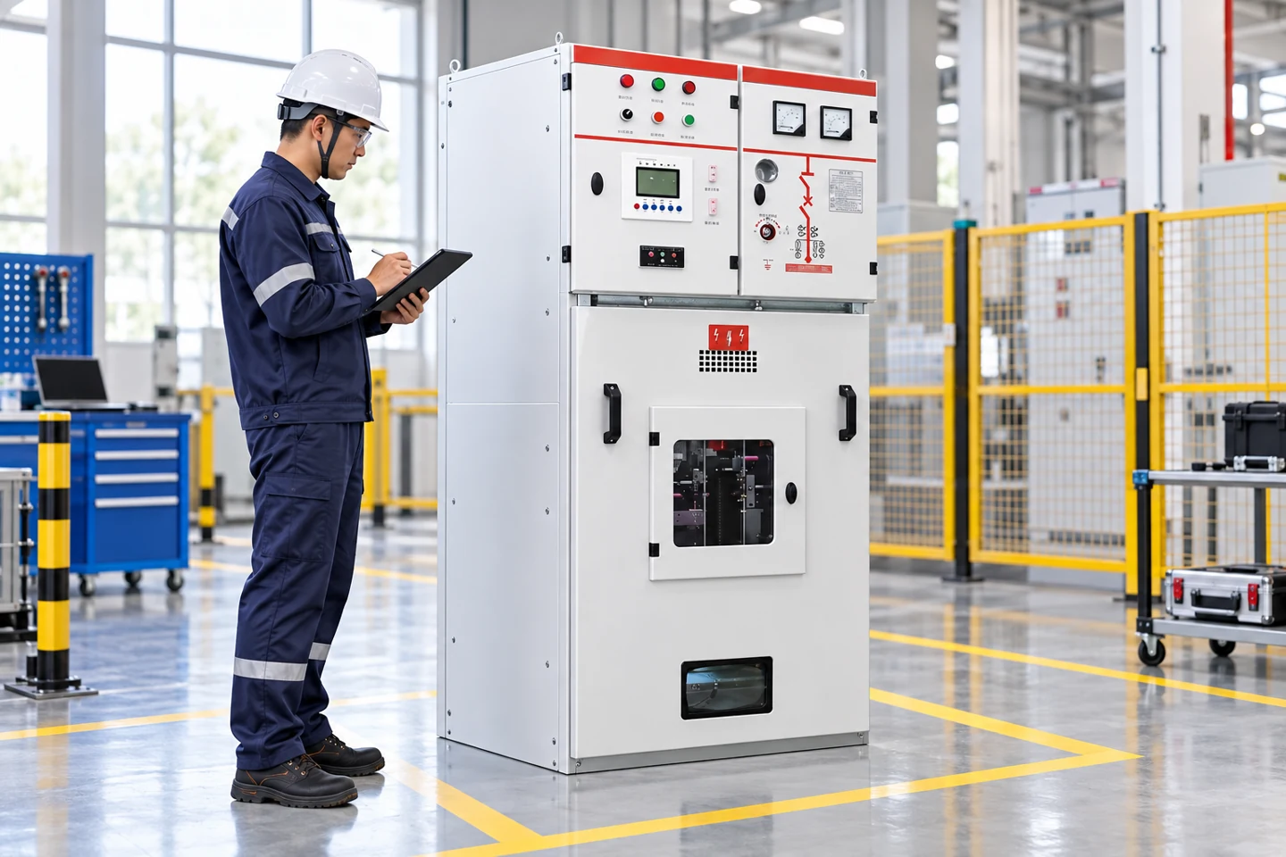
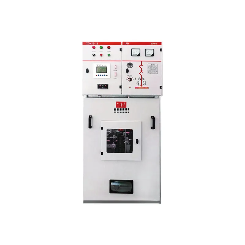
For a withdrawable or modular arrangement, verify service and test positions, shutters, position contacts and racking stops. The KYN28A-12 metal-clad switchgear page illustrates how breaker position and interlock functions are represented in a medium-voltage product family. The actual SF6 compartment and control diagram must be checked separately.
Testing and commissioning
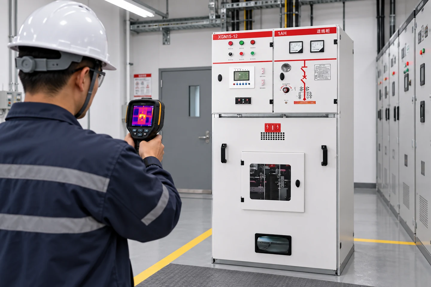
Commissioning normally includes visual inspection, nameplate verification, gas-density check, leak test, mechanical operation, contact resistance, timing, insulation and relay-function testing. Use the manufacturer’s test limits and the approved site procedure. Do not apply a test voltage or open a compartment without confirming isolation, earthing and gas-handling boundaries.
Record open and close times, pole simultaneity, trip-coil current, contact resistance, relay settings and gas-density readings. Compare results with factory data and previous maintenance records. A change in timing or density may indicate a mechanical, control or sealing problem before a visible failure occurs.
Maintenance strategy
Maintenance intervals depend on operation count, fault duty, environment and manufacturer requirements. Inspect mechanism lubrication, seals, density monitor, pressure relief, cable terminations, earthing switches and control wiring. Check for corrosion, abnormal noise, slow operation and repeated density alarms. Keep the enclosure clean and preserve the pressure-relief path.
After a fault interruption, do not simply reset the breaker. Determine the fault cause, inspect the interrupter and contacts as required, test the relay and verify gas condition. Update the single-line, event record and protection settings before returning the equipment to normal service. The switchgear testing guide explains how different tests answer different questions.
SF6 versus alternative technology
Vacuum breakers and alternative-gas or air-insulated designs may reduce greenhouse-gas concerns or simplify certain maintenance tasks. The comparison must include voltage level, fault duty, switching frequency, enclosure size, lifecycle emissions, service capability, availability and total cost. An alternative is not automatically a drop-in replacement; insulation coordination, cable interfaces and control logic may change.
When evaluating a supplier, request gas volume, leakage guarantee, density alarm thresholds, recovery procedure, type-test evidence, environmental declaration, spare parts, training and end-of-life plan. Compare the complete asset rather than only the interrupter name.
Gas-insulated equipment also needs a clear boundary between electrical and gas work. The electrical isolation, earthing and access procedure should identify pressure compartments, relief paths and any neighboring energized sections. A gas alarm does not authorize opening the tank. Follow the manufacturer’s permit and recovery process and record who performed each operation.
When a circuit breaker interrupts a fault, inspect the event record and relay targets before reclosing. Check cable terminations, current-transformer circuits and the breaker mechanism. Repeated faults can damage the interrupter or contaminate the gas compartment even when the breaker appears to operate normally. Use the specified diagnostic tests rather than relying on a visual check.
For an outdoor installation, review altitude, solar heating, salt, dust, seismic loads and drainage. Gas density varies with temperature, so alarm thresholds must match the monitor and local ambient. Keep a spare density sensor, trip coil and auxiliary-contact schedule where the asset criticality requires it. The supplier should state the gas volume and end-of-life recovery method.
Do not compare SF6 equipment only by cabinet width. Compare the complete lifecycle: losses, monitoring, leak risk, service training, recovery equipment, spare parts, type tests and end-of-life handling. A compact unit can be the right choice when the site is constrained, while an air-insulated or vacuum design may be preferable where gas handling is difficult.
Protection engineers should also review breaker-failure logic. If the primary breaker does not clear a fault, a backup breaker or bus protection scheme must trip the next source. The SF6 density alarm, trip-circuit supervision and relay communication should be included in the cause-and-effect matrix. Test these interfaces during commissioning and after a relay or control-system change.
Switching overvoltages, current chopping and capacitive or inductive load switching can affect the insulation system. Confirm the breaker application includes the specified cable, transformer, capacitor or reactor switching duty. Surge arresters, pre-insertion resistors or controlled switching may be required for a particular network. Do not infer the duty from the nominal voltage alone.
Maintain drawings that show gas compartments, pressure monitors, earthing switches, cable terminations, relief paths and control terminals. The drawing revision, nameplate, gas record and test report should identify the same asset and serial number. Good documentation reduces the chance that a later operator opens the wrong compartment or applies an unsuitable test.
Before handover, train operators on density alarms, local and remote operation, earthing-switch interlocks, emergency trip behavior and the environmental response for a suspected leak. Keep recovery equipment contacts and the asset gas log available at the site. A compact installation is only reliable when its people, procedures and records are prepared.
Where equipment is connected to a ring network, document both cable directions and the earthing sequence. An open point in the ring does not guarantee that the opposite cable is dead. Prove the switching state and apply the site isolation procedure before opening a compartment or cable termination.