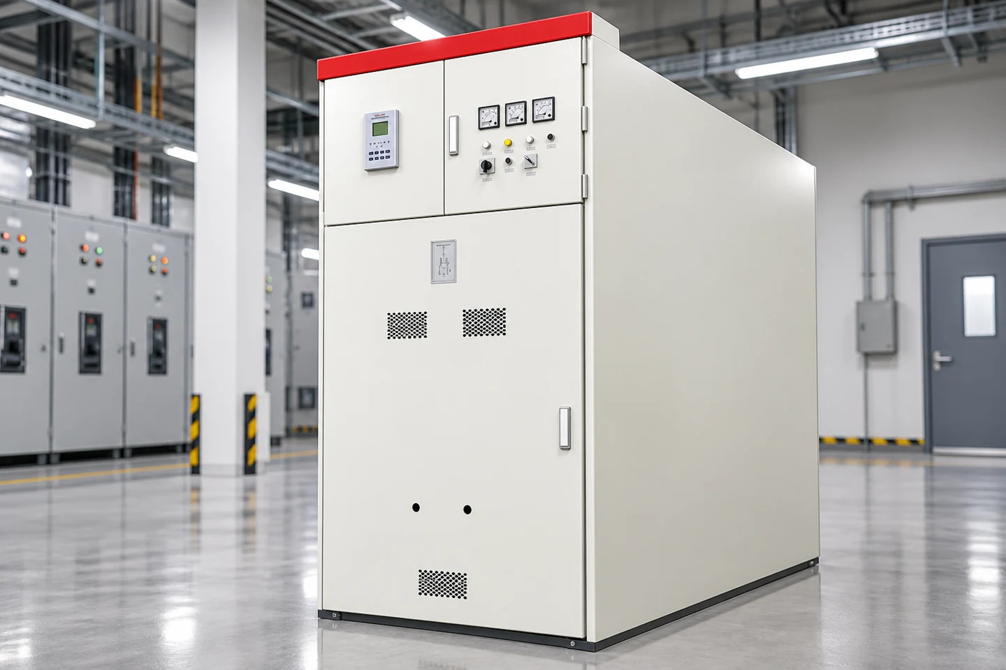
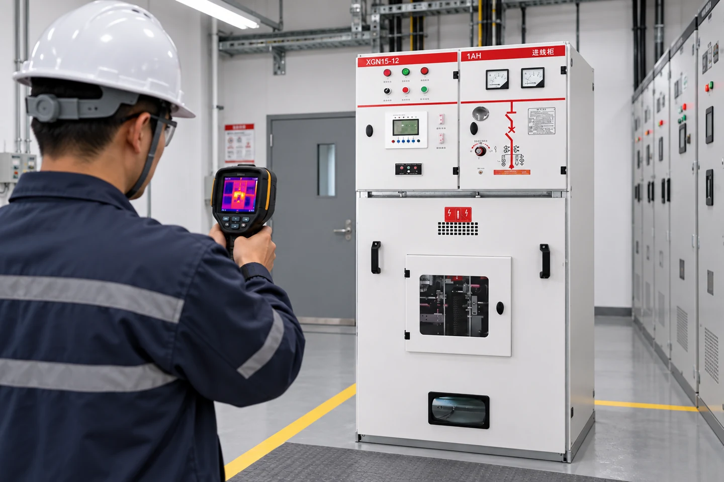
An air switch circuit breaker is an air-insulated switching and protection device that uses the surrounding air as its arc-insulation medium. The term is used for several low-voltage devices, including air circuit breakers, panel air switches and manually operated disconnects. The exact function matters: a disconnect may isolate a circuit but not interrupt a fault, while an air circuit breaker is designed to interrupt load and short-circuit current within its rating.
Define the device before selecting it
Start by identifying whether the equipment is an air circuit breaker, molded-case breaker, switch disconnector or fused switch. Check the rated operational voltage, insulation voltage, frequency, continuous current, short-circuit breaking capacity, short-time withstand and pole arrangement. A product described only as an “air switch” is not enough information for a procurement specification.
| Parameter | Question | Verification |
|---|---|---|
| Function | Does it switch load, isolate, or interrupt faults? | Product standard and data sheet |
| Continuous current | What current can the frame carry in the enclosure? | Rated current and temperature derating |
| Breaking capacity | What fault current can it interrupt at system voltage? | Test rating and fault study |
| Trip unit | Are long-time, short-time, instantaneous or ground-fault functions required? | Trip-unit schedule and settings |
| Isolation | Can the device provide the required visible or lockable isolation? | Switching diagram and local code |
How air interruption works
When contacts separate, an arc forms between them. Arc runners, magnetic forces, splitter plates and the arc chamber lengthen, cool and divide the arc until it can no longer sustain current. The design must withstand recovery voltage after current interruption. Unlike a fuse, the breaker can be reset and its trip behavior can be tested, but its rating still depends on the complete assembly and operating conditions.
Air circuit breakers often use stored-energy mechanisms and electronic trip units. The mechanism may be manually charged or motor charged, and closing may require a permissive or undervoltage release. Auxiliary contacts report open, closed and tripped states. Confirm the control voltage, terminal numbering and remote-control logic from the exact model diagram.
Protection functions
A typical electronic trip unit provides long-time protection for overload, short-time protection for coordination, instantaneous protection for high faults and optional ground-fault protection. The settings must be coordinated with downstream breakers and upstream sources. Do not raise instantaneous pickup just to prevent nuisance trips without checking arc energy, conductor protection and the available fault current.
Generators, transformers, motors and photovoltaic inverters can contribute fault current or change the current waveform. Review normal, standby and transfer modes. A setting that is selective on utility supply may not be selective when a generator is connected. Keep the approved time-current curves and setting record with the panel.
Air switch versus molded-case breaker
Large air circuit breakers are commonly used as mains and major feeders, where adjustable protection, high current, short-time withstand and withdrawable construction are valuable. An MCCB is usually more compact and may be suitable for smaller feeders. A switch disconnector may be appropriate for isolation but may need a separate fuse or breaker to clear faults. Compare the actual standards and ratings instead of relying on names.
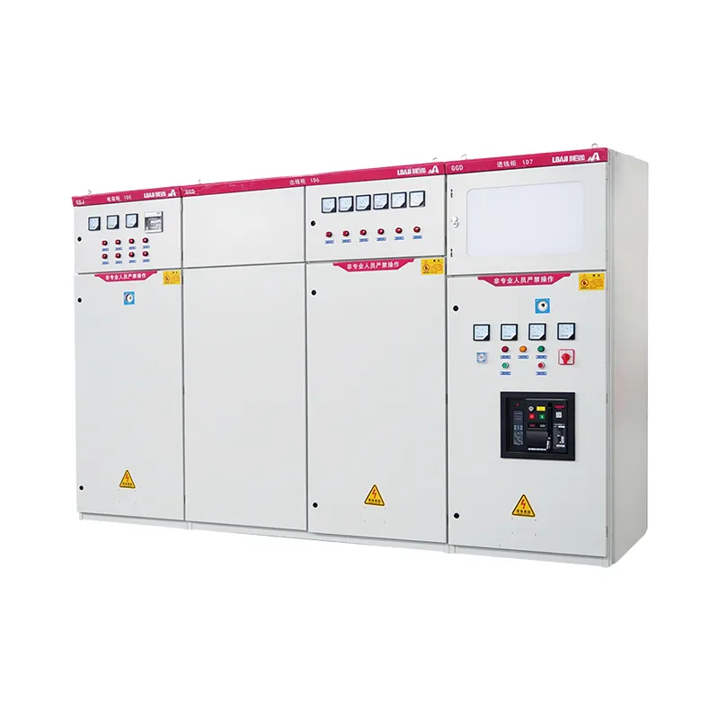
The panel assembly also matters. Busbar temperature, ventilation, cable terminals, barriers and arc-containment features can limit the practical rating. The LBAJI GGD low-voltage switchgear page is a product reference; the approved drawing must identify the installed breaker and trip unit.
Installation and wiring
Follow the manufacturer’s torque, clearance, cable-entry and mounting requirements. Keep control wiring separated from power conductors, identify every auxiliary terminal and provide a protected control supply. If a shunt trip or undervoltage release is fitted, document its fail state and reset behavior. A remote trip command is not equivalent to lockout and absence-of-voltage verification.
For withdrawable designs, verify connected, test and isolated positions, shutters, racking interlocks and position contacts. The MNS/GCK/GCS switchgear family shows why feeder position is part of the electrical safety boundary. The breaker, cradle and bus connection must be the approved combination.
Fault rating and coordination
Calculate prospective short-circuit current at the installation point, including utility, transformer, generators, motors and alternate sources. Confirm the breaker interrupting capacity at the actual voltage. Then verify the assembly short-circuit rating, short-time withstand and any series-rating restrictions. A device rated for a lower voltage may have a different breaking capacity at the project voltage.
Selective coordination uses time-current curves, manufacturer tables or an engineered study. The main breaker should not trip before a downstream feeder when the design intent is selective clearing. Ground-fault settings need special attention in multi-source systems because neutral and bonding arrangements affect the sensed current.
Commissioning
Before energizing, inspect barriers, torque, labels, earth continuity, mechanism operation and trip-unit settings. Test open, close, trip, anti-pumping, shunt-trip, undervoltage and auxiliary contacts as applicable. Verify the control-source voltage at the accessory during operation. Record timing and contact resistance only with the manufacturer’s approved method.
Run the breaker under representative load and check temperature at terminals and bus connections. A first successful operation does not prove coordination. Investigate hot spots, delayed operation, unexpected alarms or a mismatch between local and remote status before placing the panel in service.
Maintenance
Maintenance includes cleaning the arc chamber, inspecting contacts, checking mechanism lubrication, exercising the breaker, verifying trip settings and testing accessories. Dust, moisture and corrosion can reduce insulation and interrupting performance. Follow the device manufacturer’s intervals and safe isolation procedure. Keep a record of operations, faults, test results and setting changes.
If the breaker is replaced, verify frame, trip unit, terminals, cradle, accessories and assembly rating. Update the single-line, panel label and arc-flash study. The switchgear testing guide explains why visual, insulation, contact and functional tests should be documented separately.
Procurement checklist
Ask for rated voltage, insulation level, current, breaking capacity, short-time withstand, trip functions, accessory list, control voltage, enclosure compatibility, withdrawable options, test standard and ambient derating. Request the exact dimensional drawing and terminal schedule. Define whether the device is for switching, isolation, protection or all three. This prevents a disconnect from being substituted for a fault-interrupting breaker.
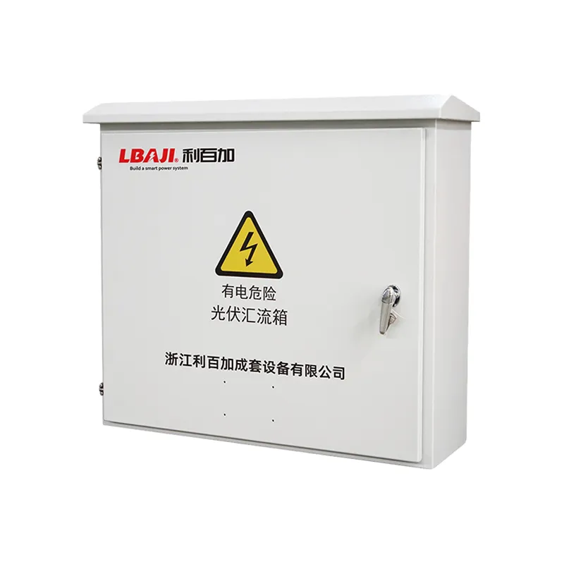
For packaged renewable-energy or substation equipment, include backfeed, inverter fault behavior and outdoor environment. The BWG-800 cabinet is a product-family reference, not a generic air-breaker specification. The approved single-line and protection study control the final choice.
Air-breaker selection also affects arc-flash exposure. Record the clearing time, trip settings, working distance, enclosure type and maintenance state used in the incident-energy study. A replacement breaker with a different instantaneous function can change the label even when the continuous current is unchanged. Keep labels and settings synchronized with the current equipment.
For a main incomer, review backfeed from generators, UPS systems and photovoltaic converters. Mechanical and electrical interlocks should prevent unsafe parallel operation unless the design explicitly permits it. Test the transfer sequence, remote trip and source indication with the control-system engineer. A breaker that opens one source may leave another source energized.
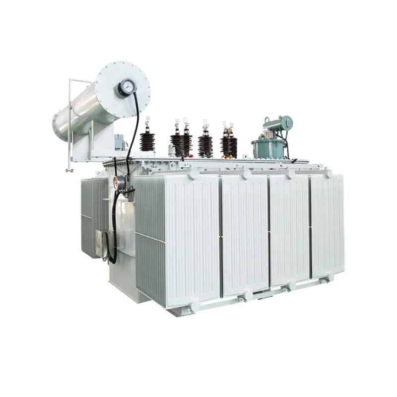
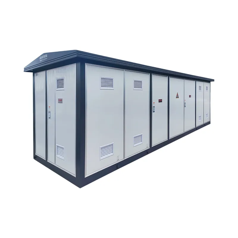
When the device is installed in a prefabricated substation, verify the low-voltage compartment, transformer impedance, cable termination and outdoor ambient. The YBM-12 substation illustrates a packaged enclosure, but the approved internal schedule controls the air-breaker specification. Ask for the factory routine-test record and the final as-built drawing before energization.
During a retrofit, inspect the busbar, cable lugs and compartment temperature before increasing the breaker frame. A larger air breaker can require different clearances, a stronger chassis and revised barriers. Confirm the short-time withstand of the bus assembly and the mechanical strength of the connection. Update the panel schedule and spare-parts list after the change.
Operators should see a clear distinction between open, closed, tripped and isolated states. Use durable labels and a local indication that agrees with the auxiliary contacts. If the breaker is controlled by a PLC, test loss of communication, loss of control power and a manual emergency trip. A remote status word is not a substitute for the physical position indication required by the procedure.
Keep the final specification neutral and traceable. State the standard, ratings, trip functions, accessories, environment, assembly type, tests and documents required. This prevents a visually similar switch from being substituted for a fault-rated circuit breaker and gives maintenance staff the information needed to plan isolation and testing.
Include a clear safe-work boundary in the operating manual: which source is isolated, where the breaker can be locked, how absence of voltage is verified and which stored-energy or alternate-source checks are required. This is essential when the air breaker is part of a transfer, generator or renewable-energy system.
Keep an approved spare strategy for the breaker frame, trip unit, closing coil and auxiliary contacts. Substituting an unlisted accessory can change the tested combination and the control logic. Record the part numbers and compatibility notes in the maintenance system before commissioning.