A voltage drop and resistance calculator applies Ohm’s law to a defined circuit. For a resistor or a known circuit section, voltage drop is Vdrop = I × R, where current is in amperes and resistance is in ohms. The result only makes sense when the current path, conductor resistance, temperature, connection resistance and AC or DC conditions are defined. A calculator gives a transparent estimate; it does not replace conductor sizing or a field measurement.
For measurement context, Fluke’s voltage-drop troubleshooting reference explains why current must flow during a meaningful drop test and why resistance in wires and connections affects the result. The article is a measurement reference, not a substitute for the wiring rule or acceptance limit governing your project.
Use the right inputs
Enter current in amperes and resistance in ohms. If the resistance is given in milliohms, convert it to ohms before calculating. If a cable’s resistance is provided per unit length, multiply by the complete current-path length and account for both outgoing and returning conductors where appropriate. For a three-phase circuit, use the formula and impedance convention specified by the design method; do not substitute a single-phase loop formula without checking the system.
| المدخلات | Meaning | Typical mistake |
|---|---|---|
| I | Current through the section, in A | Using a nameplate maximum when the calculation needs operating or design current |
| R | Resistance of the complete section, in Ω | Using mΩ as Ω or forgetting the return conductor |
| Vdrop | Lost voltage, in V | Confusing drop with the source voltage |
| Vsource | Voltage at the sending end | Ignoring supply tolerance or transformer impedance |
| Vتحميل | Voltage remaining at the load | Not checking the equipment’s minimum operating voltage |
The basic relationships are Vdrop = I × R and Vتحميل = Vsource − Vdrop. If you know the allowed drop and current, the maximum resistance is Rmax = Vdrop,max/I. Keep units visible in the calculation so a tenfold or thousandfold error is obvious.
Worked resistor example
Suppose a DC control circuit carries 2 A through a measured 0.35 Ω resistance. The calculated drop is 2 × 0.35 = 0.70 V. With a 24 V source, the load receives approximately 23.30 V before any additional terminal, fuse or supply variation. If the load requires at least 22.8 V, the arithmetic result leaves 0.5 V of margin, but the designer should still check starting current, temperature and the power supply’s regulation.
For a second check, if a 10 A circuit may lose no more than 1.2 V, the complete circuit resistance should not exceed 1.2/10 = 0.12 Ω. That value includes conductors and relevant connections. A calculator cannot tell you whether a particular cable size has that resistance at its operating temperature or whether its protective device is correctly selected. Use the manufacturer’s conductor data and the applicable wiring rule.
Series and parallel resistance
For series resistances, Rالمجموع = R1 + R2 + …, so each element’s drop is I × Rn. The largest resistance takes the largest share of the drop. For two parallel resistors, 1/Rالمجموع = 1/R1 + 1/R2. Current divides between branches, so calculate each branch using its own current and resistance. Do not add parallel branch resistances as though they were in series.
In a panel, contacts, fuses, terminal blocks, cable lugs and conductor runs can all contribute resistance. A loose or corroded connection may produce a local hot spot even when the total voltage drop looks acceptable. Record the test current, meter lead placement and temperature if measuring a connection. The resistor voltage-drop article gives the basic Ohm’s-law relationship; this guide adds wiring-path and design limitations.
AC circuits need impedance, not resistance alone
In AC power circuits, voltage drop depends on resistance, reactance, current, power factor, phase arrangement and conductor geometry. A motor feeder may have a significant reactive component, especially during starting. A simple I × R calculator can understate the drop if it ignores reactance. Use the cable manufacturer’s impedance data and the method required by the project standard. For three-phase circuits, verify whether the design uses line-to-line voltage, line current and the correct length factor.
Transformers, drives and power supplies add their own impedance and inrush effects. A 24 V control supply may appear adequate at steady state but collapse during a solenoid or contactor pull-in. Measure or calculate the worst operating condition, not only the average. Separate steady-state drop from transient behavior in the design record.

Check the result against the equipment
Compare the calculated load voltage with the device’s operating range, pickup voltage, reset voltage and undervoltage behavior. Check lighting performance, motor torque, drive alarms and relay operation where relevant. If the drop is excessive, consider a larger conductor, shorter run, different source arrangement, local control supply or revised protection. Do not increase a breaker simply to hide a voltage-drop problem; protection must still match the conductor.
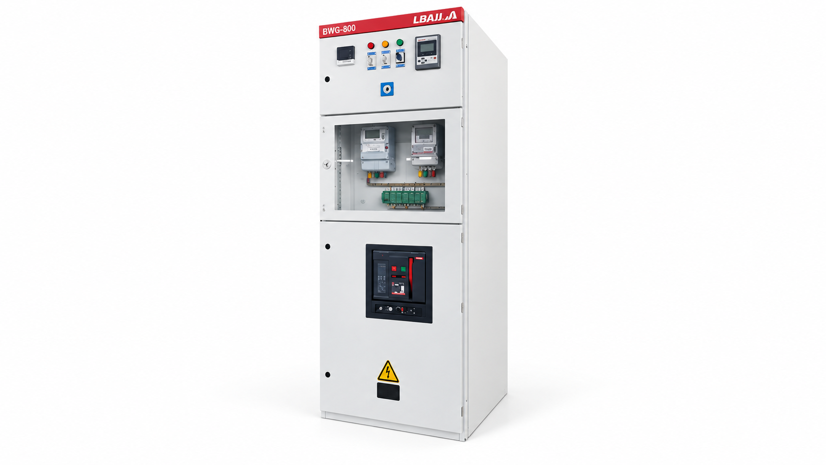
For a distribution cabinet such as the LBAJI GGD low-voltage switchgear, identify the exact feeder and terminal path before calculating. A packaged unit such as the محطة الطاقة الكهربائية YBM-12 may include transformer impedance that cannot be omitted. The product photo does not provide the cable length, conductor size or operating current needed for a valid calculation.

Measure and document
Use a calibrated meter appropriate to the circuit and safe-work method. Measure source voltage, load voltage and current under the condition being investigated. A four-wire resistance measurement can reduce lead-resistance error for low-ohm connections. Record temperature, load state, conductor identity, test points and instrument. Recheck after tightening or replacing a connection and keep the original reading.
Voltage-drop calculations are most useful when the assumptions remain visible. Save the formula, units, cable data, length, design current, power factor or impedance method, source tolerance and acceptance limit with the drawing revision. The testing guide explains why a measured value needs its method and context before it can be trusted.
Temperature and conductor data
Metal resistance changes with temperature, so a conductor that meets a cold-room estimate may have a larger drop at its operating temperature. Use the conductor manufacturer’s resistance data at the relevant temperature or apply the correction required by the applicable wiring rule. Account for parallel conductors only when they are installed, terminated and protected as a proper parallel set. A calculator should state whether its resistance is at 20 °C, operating temperature or a measured field condition.
Terminations deserve the same attention as cable length. A long, correctly sized conductor can still show a local voltage drop or heating problem at a loose lug, corroded terminal or undersized connector. Compare phase and pole readings under the same load. If one connection differs materially from its peers, investigate the connection and instrument setup rather than averaging the values away. Record any repair and repeat the measurement with the same method.
For motors, consider starting current and the resulting temporary drop. A feeder can satisfy a steady-state percentage target yet cause a contactor to chatter or a drive to fault during acceleration. For electronic loads, check the manufacturer’s minimum input and ride-through requirement. If a local control supply is used, calculate its source, cable, fuse and return path as a complete circuit. The result should be reviewed with the equipment designer before a cable or transformer is changed.
When a calculator result looks wrong
First recheck units, especially milliohms, millivolts, metres and kilometres. Then check whether the current is RMS, starting, peak or steady-state. Confirm the complete loop length, conductor temperature, parallel paths and whether the resistance belongs to one phase, one conductor or the whole circuit. In an AC calculation, confirm the phase and power-factor convention. A result that is implausibly high or low is usually a definition problem before it is a mathematical problem.
Compare calculated and measured voltage at the same load condition. If the calculated value is small but the measured drop is large, inspect terminals, fuses, disconnects, contactors and cable lugs for resistance. If the measured value changes with instrument placement, the measurement method may be including or excluding a connection. Preserve the original readings and test setup so another technician can reproduce the finding.
Use a conservative design current when the load profile is uncertain, and document the assumption. A future motor, heater, inverter or longer cable route can change the result. Recalculate after a transformer change, feeder extension, parallel-conductor change, protection upgrade or new distributed-energy source. A spreadsheet or calculator is most useful when it becomes part of the controlled design record rather than a one-time number copied into a quotation.
Further viewing: An educational circuit-analysis lesson can help visualize current and voltage relationships; use the project calculation method for actual cable selection.