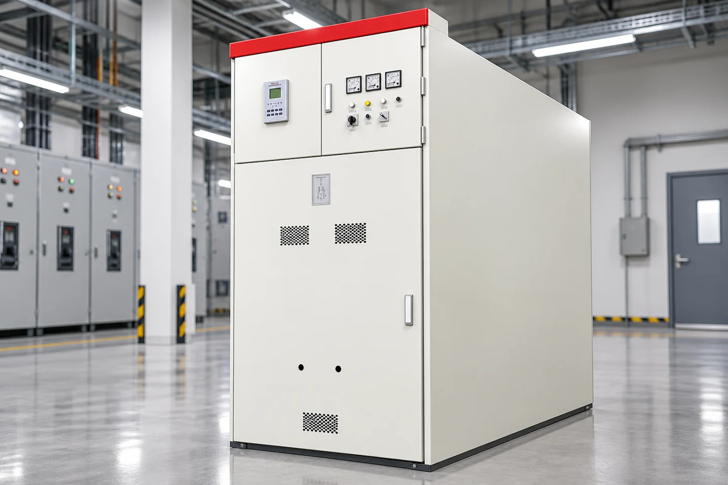
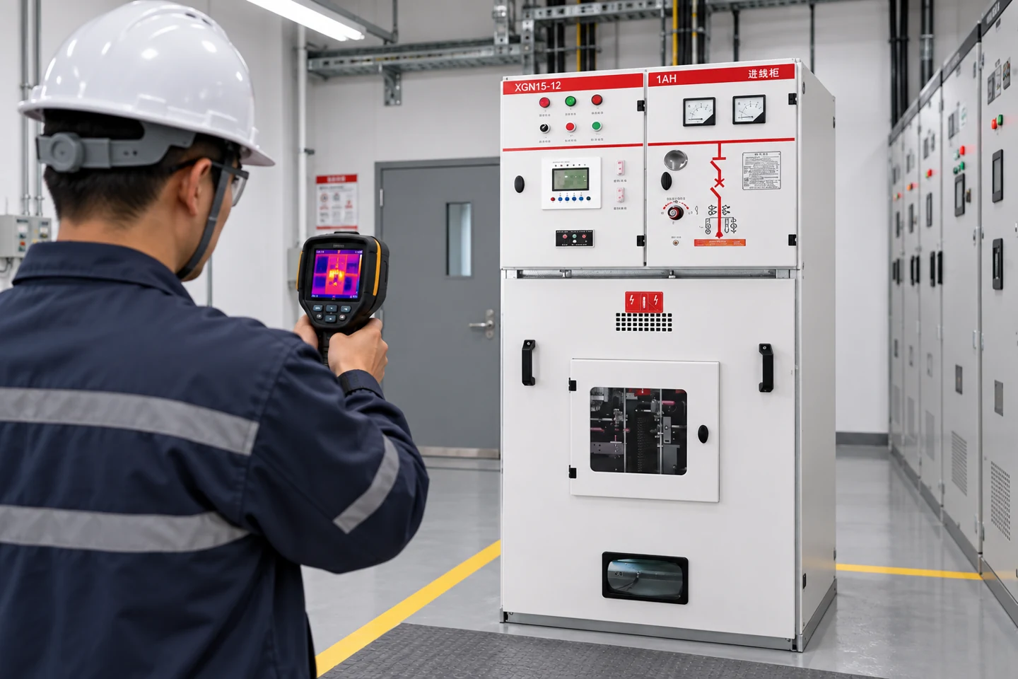
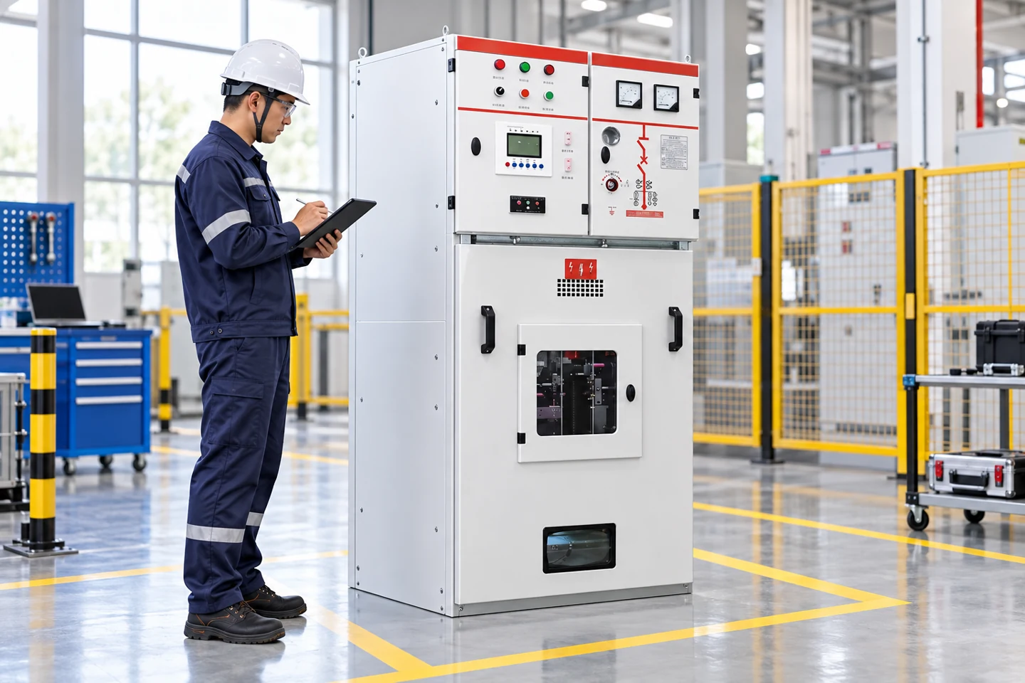
Ring main units (RMUs) in electrical distribution are compact medium-voltage assemblies used to switch, protect and sectionalize ring or radial feeders. An RMU normally combines load-break switches, an earth switch, cable terminations and—where required—a fused or circuit-breaker tee-off. This guide explains RMU operating states, ratings, protection, installation, maintenance and procurement decisions for distribution networks.
RMU selection in brief
- Confirm voltage, continuous current, short-time withstand and fault-interruption duty before comparing models.
- Match the RMU insulation system and enclosure to humidity, dust, salt, altitude and access conditions.
- Coordinate ring switches, transformer protection, earthing and remote indication on the one-line diagram.
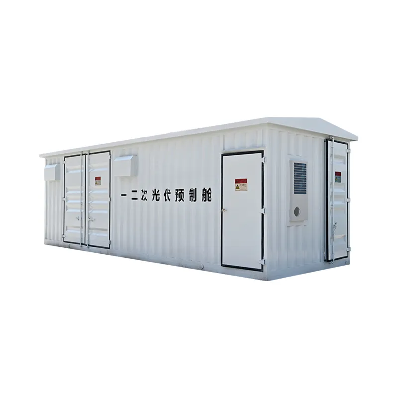
What Is Air-Insulated Switchgear?
AIS uses atmospheric air as the principal external insulation between energized parts and earth. Indoor medium-voltage AIS commonly has separate breaker, busbar, cable and low-voltage compartments. Outdoor high-voltage AIS uses bus conductors and equipment separated by open-air clearances.
Its strengths include visible construction, familiar maintenance, easier component access and often lower initial equipment cost. Its disadvantages are larger footprint and greater sensitivity to dust, salt, humidity, condensation and small animals if the enclosure or building is not controlled.
What Is Gas-Insulated Switchgear?
GIS encloses primary conductors, switching devices and busbars inside sealed grounded compartments. The controlled insulating medium permits smaller clearances, creating compact equipment resistant to external contamination. GIS is common where land is expensive, space is limited or the environment is severe.
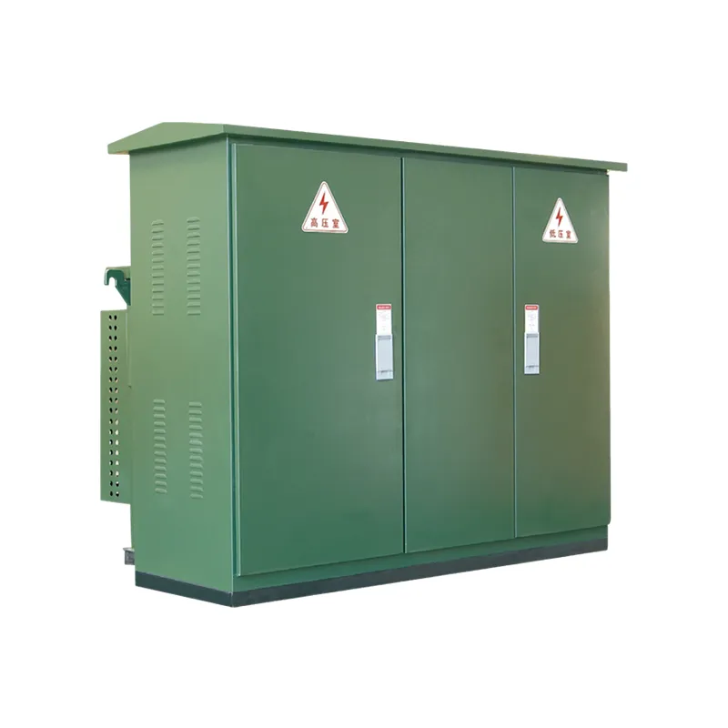
GIS vs AIS Comparison
| Factor | GIS | AIS |
|---|---|---|
| Footprint | Compact | Larger |
| Environmental exposure | Primary parts sealed | More exposed to air and contamination |
| Visual access | Limited | Greater |
| Routine primary maintenance | Often lower | Generally more accessible |
| Specialized service | Gas/sealed-module skills | Conventional air-insulated skills |
| Initial equipment cost | Often higher | Often lower |
| Land/building cost | Often lower footprint cost | Greater space requirement |
Footprint and Layout
GIS can dramatically reduce bay width and building area. However, total project footprint must include cable terminations, gas zones, pressure relief, lifting space and future extensions. AIS needs greater electrical clearance but can offer straightforward access and simpler building interfaces.
Reliability in Harsh Environments
Sealed GIS is attractive for coastal salt, industrial pollution, dust, high humidity and confined underground sites. AIS can also perform reliably when enclosure, heaters, ventilation, creepage distance and maintenance match the environment. Neither technology compensates for poor cable sealing or inadequate room control.
SF6 and Environmental Considerations
SF6 has excellent dielectric and arc-quenching properties but a very high global-warming impact. Projects using SF6 should define leakage limits, density monitoring, trained handling, recovery, reporting and end-of-life treatment. Regulations differ and continue to evolve.
Alternative designs use lower-GWP gas mixtures, clean air, vacuum interruption and solid insulation. “SF6-free” does not automatically prove overall environmental superiority; compare insulating medium, material use, losses, service life, repairability and recycling.
Maintenance and Diagnostics
AIS maintenance includes cleaning, insulation inspection, mechanism service, contact resistance, breaker timing, thermography and partial-discharge assessment. GIS reduces exposure of primary parts but requires density/pressure checks, leak monitoring, mechanism service and specialized intervention if an internal sealed component fails.
Internal-Arc and Operator Safety
Both GIS and AIS can be tested for internal-arc performance. Specify accessibility sides, arc current, duration and installation conditions. Pressure-relief ducts and room volume must match the tested arrangement. Internal-arc classification reduces consequences under defined conditions but does not replace isolation, grounding, remote operation and safe work procedures.
Lifecycle Cost
Compare equipment, land/building, installation, outages, maintenance, gas management, spares, training and disposal. GIS may justify higher purchase price by reducing footprint and environmental maintenance. AIS may offer lower cost and easier repair where space and conditions are favorable.
Product Options
For conventional 12 kV metal-clad AIS, review KYN28A-12 switchgear. Compact sealed networks can use the LBHB-12 environmentally friendly RMU. For 40.5 kV applications, compare KYN61-40.5 AIS with HC-40.5 sealed ring-network switchgear.
Selection Checklist
- Voltage, current, insulation and fault ratings.
- Available room/land and future extension.
- Pollution, humidity, altitude and temperature.
- Internal-arc and pressure-relief requirements.
- Protection, cable and communication interfaces.
- Local gas regulations and environmental targets.
- Maintenance skills, spares and outage strategy.
- Complete lifecycle cost and end-of-life plan.
Main components of gas-insulated switchgear
GIS integrates busbars, circuit breakers, disconnectors, earthing switches, CTs, VTs, cable or bushing interfaces and gas compartments in grounded metal enclosures. Density or pressure monitoring, interlocks and relief arrangements are part of the primary safety system.
Questions to ask before choosing GIS
Confirm footprint and extension needs, gas or alternative insulation policy, leakage guarantees, environmental reporting, spare modules, cable interfaces, outage strategy and local service capability. Compact size is valuable, but lifecycle access and future bay additions can dominate the project decision.
Technical references and further reading
The following independent sources support the standards, terminology, calculations, and safety context discussed in this guide:
- IEC 62271-200 metal-enclosed switchgear standard — Scope, classifications, service conditions, internal-arc testing, interlocks, and requirements for AC metal-enclosed switchgear up to 52 kV.
- IEEE C37.121 guide for switchgear-unit substations — Coordination guidance for switchgear and transformer sections in three-phase unit substations.
- OSHA electrical power safety requirements — Safety requirements for construction involving electric power transmission and distribution equipment.
RMU operating sequence and interlocks
Before energizing an RMU, verify that the approved switching schedule identifies the source feeder, load feeder, transformer tee-off and earth switch positions. A typical ring path is open at one point during normal operation, then closed at a different point after an outage to restore supply. The interlock system must prevent an earth switch from closing onto an energized cable and prevent a load-break switch from being operated outside its rated duty. Key indications should be visible locally and, where specified, through remote contacts.
Protection settings are not interchangeable between an RMU and the upstream relay. A fused tee-off may use a fuse curve coordinated with transformer inrush, while a circuit-breaker tee-off needs relay pickup, time delay and earth-fault settings. Confirm cable-screen bonding, zero-sequence CT placement and the utility’s earth-fault philosophy. Record the final settings on the as-built drawing.
Installation and commissioning checklist
Check the foundation, anchoring, cable trench, minimum bending radius, phase identification and termination kit before the RMU arrives. Keep the enclosure level and protect bushings from dust and moisture during cable work. During commissioning, inspect torque records, insulation resistance, contact resistance, mechanical operation, interlocks, phase sequence, earth continuity and remote indications. Perform high-voltage or withstand tests only with the approved method, test limits and isolation controls.
For gas-insulated RMUs, record the nameplate medium, density or pressure indication and any alarm contact. Do not release gas or open a sealed compartment without the manufacturer procedure and trained personnel. For solid-insulated or air-insulated designs, inspect shutters, barriers, heaters and condensation controls. The maintenance interval should follow the duty and environment rather than a generic calendar alone.
Maintenance and failure diagnosis
Routine maintenance includes visual inspection, cleaning of cable compartments, exercising switches, checking earth-switch operation, inspecting fuse indicators and verifying labels. Investigate a partial-discharge alarm, abnormal temperature, pressure loss, moisture or unexplained protection trip before returning the unit to service. A failed ring section can often be isolated while the healthy section remains energized, but the switching plan must be approved and the faulted cable proven dead.
When specifying an RMU, ask for type-test evidence, routine-test records, internal-arc classification where required, spare-part availability, service response and end-of-life instructions. Compare the complete installed cost—cable accessories, civil work, protection, monitoring and training—not only the enclosure price. These checks reduce the risk of choosing a compact unit that cannot be safely maintained in the actual network.
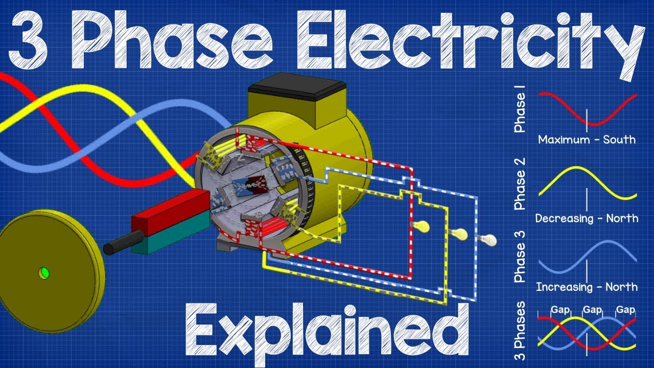
Neutral technical video
This neutral educational video provides background on medium-voltage switchgear operation. Use the project drawings, manufacturer manual and qualified-person procedures for the actual RMU.
Finally, document the normal open point, alternate supply path, earthing points and switching authority on a simple network diagram. A clear diagram helps operators restore supply without closing two sources unintentionally. Include the RMU serial number, cable identifiers, protection settings and latest test date so the field team can identify the correct compartment before work begins.