Control switchgear houses power distribution, motor control, automation, protection and operator interfaces in an engineered enclosure. A reliable panel starts with a functional description, load list and I/O schedule before component layout.
Related references include the 33kV GIS switchgear guide, the switchgear testing guide and the ring main unit guide.
Control switchgear design inputs
Define the controlled process, source and load ratings, control voltage, fault duty, operating modes, permissives, interlocks, alarm priorities, communications, environmental conditions and maintenance boundary. Separate power wiring from instrumentation and communications, provide terminal access and reserve space for heat-producing devices. The panel schedule should identify every breaker, contactor, relay, fuse, terminal and spare point.
Protection and automation are related but not interchangeable. A control command must not defeat an earth switch, door interlock or breaker trip path. Review fail-safe behavior for loss of auxiliary power, broken wire, communication failure and emergency stop. Record the expected state of each output during commissioning and maintenance.
Use a cause-and-effect matrix for trips, alarms, permissives and reset conditions. Test normal, abnormal and loss-of-supply states, then save the results with the revision-controlled drawings. This makes later troubleshooting safer because the operator can distinguish a deliberate interlock from an unexpected failure.
Review the matrix with operations and maintenance before handover. A technically correct panel can still be unsafe if operators do not know the normal state, the isolation boundary or the response to a failed permissive. Document those decisions in plain language.
Also define the control-power source, fuse coordination, terminal numbering, communication timeout and safe state for every remote function. Test the panel with the upstream device and the controlled equipment, not only on a workbench. Record measured pickup, trip, timing and indication results against the approved acceptance criteria.
Include a rollback plan for firmware or relay-setting changes and identify who authorizes the return to service. These records protect the operating team when a control sequence is changed after commissioning.
Review these results at handover and retain the signed commissioning record for future maintenance audits.
Store the signed test sheet with the panel serial number.
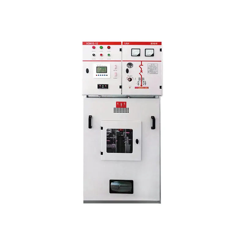
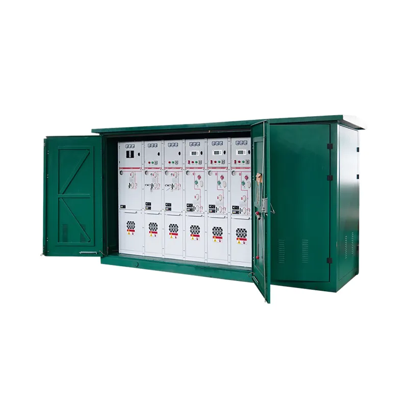
Control switchgear commissioning
Commissioning should prove local controls, remote commands, permissive logic, trip circuits, indication, interlocks, alarm contacts, CT and VT polarity, communications and fail-safe behavior. Compare every point with the I/O list and approved sequence of operation. Do not bypass a protection interlock without an approved test method.
Keep the final control schematic, terminal schedule, relay settings, test records and software revision with the equipment. During maintenance, isolate power and control sources separately, control stored energy and verify that a remote command cannot re-energize the compartment unexpectedly.
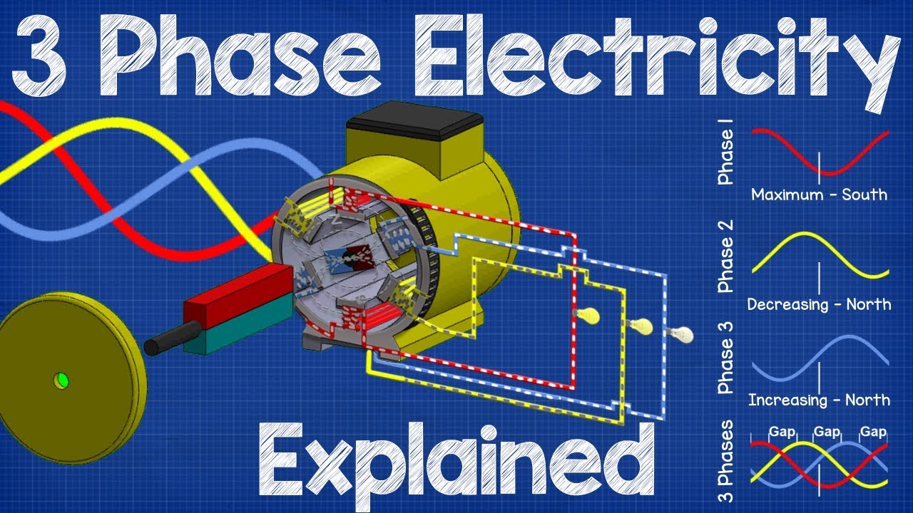
Neutral technical video
This neutral switchgear video provides general background; the installed control philosophy and safety procedure take priority.
Key Takeaways
- Start with verified system data and the governing standard.
- Coordinate ratings, protection, environment and maintenance as one decision.
- Use drawings, calculations and test records to support procurement.
Power and control architecture
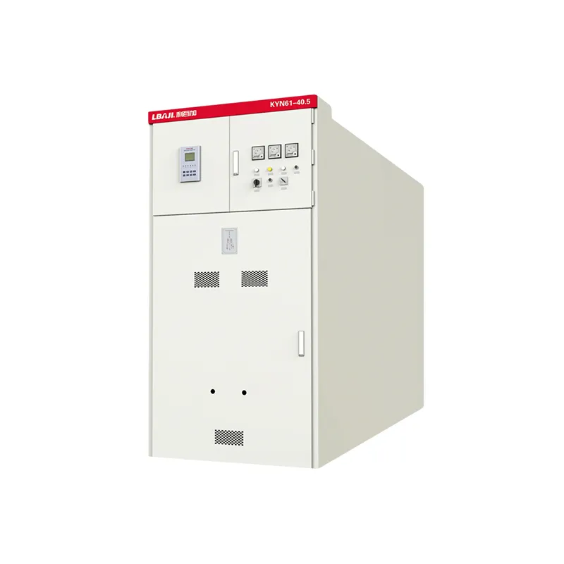
Power and control architecture defines the boundary of a sound engineering decision. Record the system voltage, phase, frequency, loading, fault duty, environment, operating history and applicable standard before selecting equipment or work scope. These inputs prevent a familiar product name from being mistaken for a complete specification.
Quick Comparison and Selection Table
Use this table as a quick review of the main engineering and procurement decisions explained in the article.
| Decision area | Practical meaning | What to verify |
|---|---|---|
| Power and control architecture | Power and control architecture defines the boundary of a sound engineering decision. | Record the system voltage, phase, frequency, loading, fault duty, environment, operating history and applicable standard before selecting equipment or work scope. |
| Breakers, contactors, drives, PLC and relays | For control switchgear, ratings and observed condition must be verified from nameplates, drawings and test evidence. | Compare measured values with factory data, prior trends and limits from the manufacturer or governing standard. |
| Schematic, wire numbering and terminals | The design must coordinate conductors, insulation, protection, switching and grounding as one system. | Check normal current, temporary duty, available short-circuit current, temperature rise and clearances. |
| SCCR, heat and enclosure design | Safety and reliability depend on the actual installation. | De-energization, lockout, stored-energy control, grounding and qualified-person requirements apply before inspection or service. |
| Safety circuits and human interface | Compare alternatives on lifecycle consequences: losses, downtime exposure, spare availability, maintainability, footprint, documentation and expected service life. | The lowest initial price can be the highest-cost option when it creates incompatibility, extended outages or unverifiable performance. |
Breakers, contactors, drives, PLC and relays
For control switchgear, ratings and observed condition must be verified from nameplates, drawings and test evidence. Compare measured values with factory data, prior trends and limits from the manufacturer or governing standard. A single measurement rarely proves fitness; repeatability, test conditions and trend direction matter.
For a project-specific comparison, record assumptions and have the final design reviewed by qualified electrical personnel. This is especially important where fault energy, medium voltage, utility interfaces or energized work are involved.
Schematic, wire numbering and terminals
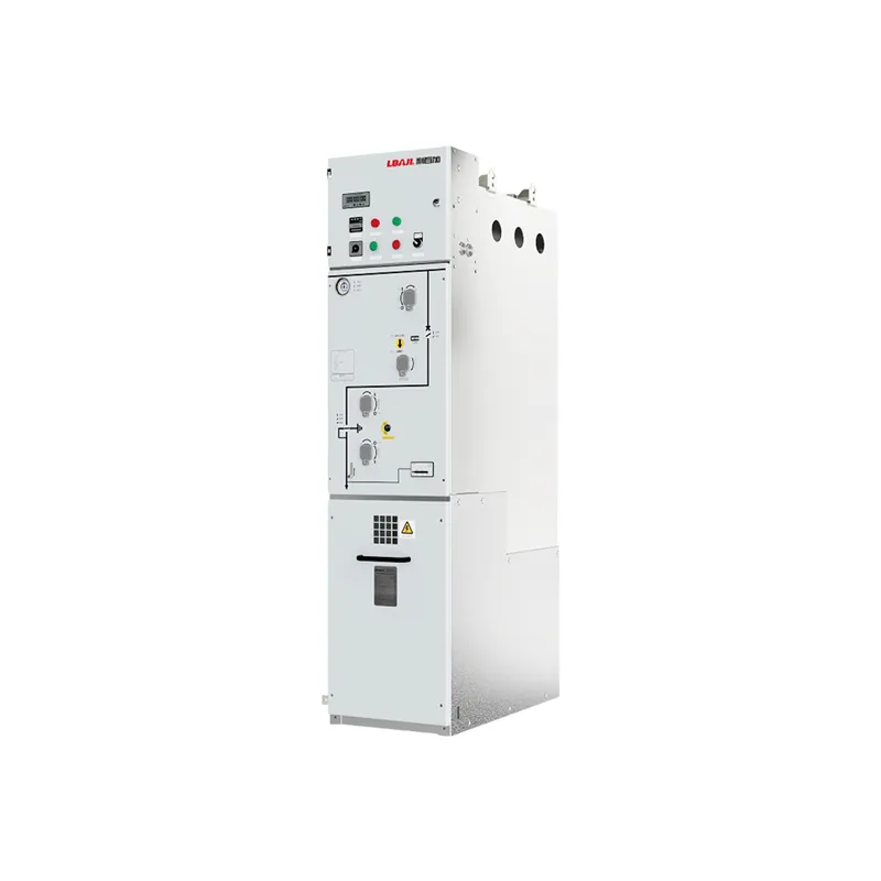
The design must coordinate conductors, insulation, protection, switching and grounding as one system. Check normal current, temporary duty, available short-circuit current, temperature rise and clearances. Accessories should solve a stated operating or monitoring need rather than be copied from another project.
SCCR, heat and enclosure design
Safety and reliability depend on the actual installation. De-energization, lockout, stored-energy control, grounding and qualified-person requirements apply before inspection or service. Where energized diagnostics are justified, use a formal risk assessment, suitable instruments and site procedures.
For a project-specific comparison, record assumptions and have the final design reviewed by qualified electrical personnel. This is especially important where fault energy, medium voltage, utility interfaces or energized work are involved.
Safety circuits and human interface
Compare alternatives on lifecycle consequences: losses, downtime exposure, spare availability, maintainability, footprint, documentation and expected service life. The lowest initial price can be the highest-cost option when it creates incompatibility, extended outages or unverifiable performance.
Manufacturing tests and documentation
A purchase or service request should state scope, ratings, standards, drawings, tests, acceptance criteria, records and warranty. Require deviations to be listed explicitly. Before energization, reconcile the supplied nameplate and test reports with the approved design and retain a baseline for future maintenance.
What the Current Google Results Commonly Emphasize
Our review of the current U.S. top-20 results found recurring coverage around 3. Electrical Components of a Control Panel, 3.8. Human Machine Interface (HMI), 3.6. Relays and Contactors, 1. What is an Enclosure?, 3.4. Terminal Block. This guide incorporates those decision points while keeping the scope focused on industrial procurement and engineering use.
Related LBAJI Equipment
Review the relevant LBAJI product range and the supporting General Electrical Knowledge pillar guide. Send the one-line diagram, ratings, quantity and environment for a project-specific configuration.
Practical Evaluation Workflow
For control switchgear, use a documented workflow rather than a catalogue-only choice. First freeze system inputs and operating limits. Next compare the available construction or service options against the actual environment. Then verify calculations, protection interfaces and acceptance tests. Finally, record approved deviations and preserve baseline results for commissioning and maintenance.
- Review breakers, contactors, drives, plc and relays and record the project-specific decision.
- Review schematic, wire numbering and terminals and record the project-specific decision.
- Review sccr, heat and enclosure design and record the project-specific decision.
- Review safety circuits and human interface and record the project-specific decision.
Acceptance Records to Keep
Retain the approved data sheet, drawings, deviation list, material certificates where applicable, routine and special test reports, protection settings, commissioning results, photographs and final nameplate details. Record test conditions as well as values, because temperature, instrument method and connection can affect comparison. These documents establish the baseline used to investigate later alarms, loading changes or deterioration. They also prevent replacement equipment from being ordered from an incomplete description after personnel or suppliers change.
Technical References and Further Reading
Conclusion
An control switchgear houses power distribution, motor control, automation, protection and operator interfaces in an engineered enclosure. A reliable panel starts with a functional description, load list and I/O schedule before component layout. Use project data and documented acceptance criteria before purchase, installation or service.