An electrical distribution construction package is the controlled set of drawings, specifications, schedules and approved supplier information used to install and verify a distribution system. It should connect the design intent to the actual equipment, cables, controls and acceptance process. A single-line diagram is an important part, but it is not the whole package. This guide explains what buyers and project teams should request, how to check consistency and how to manage the transition from issued-for-construction documents to as-built records. It is a document coordination guide, not permission to install, test or energize electrical equipment.
Define the package boundary and document status
State which system and contract the package covers. A distribution room package might include incoming equipment, transformers, a main lineup and outgoing feeder interfaces, while downstream branch circuits are covered elsewhere. List those boundaries and responsible parties. Without them, two contractors may each assume the other supplies a cable, relay interface or termination detail.
Assign a drawing and document register with identifiers, revision numbers, issue purpose and approval status. Tender, review and construction documents should be distinguishable. The latest date does not necessarily mean the document is approved for installation. A controlled register allows the site team to locate the correct version and identify superseded information. Define who can issue revisions and how affected users receive them.
Use the single-line as the system map
The single-line should identify sources, major equipment, bus sections, protective devices and load destinations within the package boundary. Match its equipment and feeder identifiers with schedules and supplier drawings. Show the intended normal source arrangement and refer to the operating narrative for alternate states. Where information is incomplete, record the outstanding design input rather than presenting an assumption as a final requirement.
The one-line supports system understanding, but it generally does not provide every terminal or physical cable route. Keep detailed construction information in the appropriate drawings and schedules. If the supplier changes a bay arrangement or device identifier, reconcile the system map and affected documents. A one-line that no longer matches the ordered equipment can confuse both commissioning and later operations.
Include the equipment schedule and technical specification
The equipment schedule should identify each assembly, location, function and relevant design requirements. Link it to the technical specification and approved data. Separate system nominal values from complete equipment ratings and verification evidence. Continuous current, insulation requirements, interrupting duty and assembly withstand are distinct questions; a short label on a drawing cannot establish all of them.
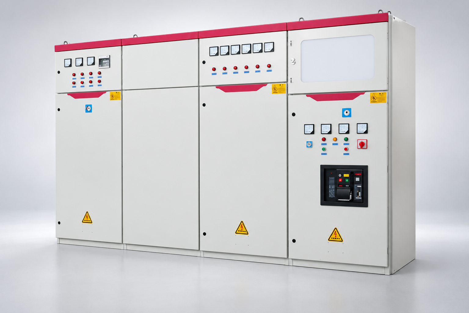
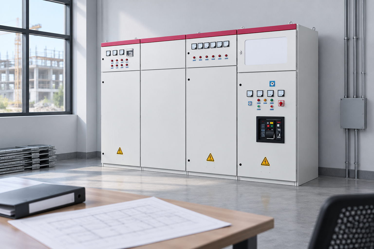
For an LBAJI GGD-based procurement discussion, request the exact proposed lineup, component configuration and documentation. The product illustration establishes a category reference, not compliance with an unidentified construction specification. The package should also define what is included in the supplier’s scope, including auxiliary devices, accessories, labels, shipping sections and manuals. Keep accepted deviations together with the final approved proposal.
Coordinate general arrangements and access
Layout drawings should show equipment positions, orientation, installation interfaces and required access. Review them with the approved supplier general arrangement, not a generic catalogue outline. Include relevant shipping-section dimensions, handling provisions, mounting details and connection locations. A cabinet that fits the final floor space may still be impossible to move through the building access route.
Coordinate cable entry, maintenance access and future replacement needs before construction. Confirm that ducts, pipes or architectural features do not conflict with the approved equipment arrangement. The applicable clearances and safety provisions require competent project review; do not invent a universal spacing from an internet diagram. Record layout decisions and update drawings when an approved equipment change affects the room.

Build a complete cable and termination schedule
A cable schedule links each circuit to its source, destination and approved cable specification. It should use identifiers that agree with the one-line and equipment labels. Include the information needed by the project, such as route reference, conductor arrangement and termination responsibility. Avoid treating a simple feeder current label as a complete cable design.
Termination drawings should identify the actual interface at each end, including control terminals where applicable. Define who supplies connectors, glands, supporting hardware and any interconnection between shipping sections. If a supplier uses a different terminal convention, reconcile it before installation. The installer should not need to infer a critical connection from similar-looking equipment or an informal message sent after the drawings were approved.
Add control schematics and operating narratives
Control documentation explains trip and close circuits, interlocks, auxiliary supplies, indications and external contacts. Match device and terminal identifiers across all sheets. Define the auxiliary supply requirements and how equipment behaves if that supply is unavailable. A note saying “automatic transfer” is insufficient without an approved sequence and interface definition.
Use an operating narrative for multi-source and transfer functions. Describe normal states, failure detection, permitted switching combinations and restoration. Distinguish the design narrative from an authorized site switching procedure. Where several suppliers share a function, identify each interface owner and test responsibility. This makes it possible to verify the whole sequence instead of receiving separate cabinet tests that leave the connections between them unexamined.
Keep studies and protection settings connected
The package should identify the system studies required by the project and the owner of each deliverable. Fault-duty assessment, coordination and other analyses support equipment and protection decisions. The construction team needs to know which assumptions are final and which must be confirmed before commissioning. A report created before a source or breaker change may need review even if its filename has not changed.
Record relay and device settings through the approved process. Identify whether settings are supplied by the manufacturer, consultant or owner, and who authorizes their use. Retain final configuration files with appropriate version control. A relay model on the bill of materials does not establish accepted settings. Site tests should connect the installed configuration to the approved study and report any differences before energization approval.
Reconcile approved supplier submittals
Supplier drawings, data and test procedures become part of the construction information only through the agreed review process. Track comments and their closure. If the supplier proposes a substitute component or arrangement, require a change record that identifies effects on ratings, controls, dimensions and acceptance evidence. A new parts list should not silently override the contract requirement.
Review the final documents as a set. Check that the approved arrangement, one-line, schematics, terminal drawings and equipment schedule describe the same configuration. Identify hold points for unresolved interfaces. UL’s information on customized equipment and field evaluation is useful when a project needs that acceptance route; it does not make every modification automatically acceptable. Keep the responsible engineering and jurisdictional decisions documented.
Define inspection, testing and energization records
Specify the factory and site acceptance scopes, witness requirements and closure process for findings. Test records should identify equipment, drawings, configuration and conditions. Separate design verification evidence from production checks and installed-system testing. A general certificate should not replace the particular evidence required by the construction specification.
Before energization, assemble the approved records and outstanding-item list through the site’s authorization process. Safety procedures and qualified work practices remain separate controlled requirements. OSHA provides relevant U.S. electrical work-practice guidance, but document completeness alone does not establish that physical equipment is safe to energize. The responsible team must verify installation, testing and operating readiness using the applicable project requirements.
Produce a usable as-built and operations handover
The as-built package should reflect accepted changes and the actual installed configuration. Collect redlines through a controlled process and verify them against final equipment identities and interfaces. Remove obsolete alternatives from the operating set while retaining the revision history. A marked-up construction drawing is useful evidence, but it should not be confused with a formally accepted final record.
Include operation and maintenance manuals, approved settings, test reports, spare-parts information and interface ownership. Make the register searchable by equipment and feeder identifiers. The operations team should be able to find the correct drawing without interpreting the construction contractor’s folder structure. Establish how future alterations update the records. A handover package stays valuable when it follows the system throughout its service life.
Construction package completeness table
| Dokument | Main question it answers | Cross-check |
|---|---|---|
| Single-line | How does power flow between sources and loads? | Equipment identifiers and feeder destinations |
| Layout and arrangement | Where and how is equipment installed? | Cable entry, access and supplier dimensions |
| Cable schedule | What connects each interface? | Circuit tags and termination responsibility |
| Control drawings | How do commands, protection and interlocks operate? | Logic narrative and external interfaces |
| Studies and settings | What supports ratings and protection decisions? | Final sources, devices and configurations |
| Test and as-built records | What was supplied, installed and accepted? | Equipment identity, revisions and closure evidence |
Häufig gestellte Fragen
Is a single-line diagram a complete construction package?
No. It maps the system, but construction normally needs layouts, cable schedules, terminal details, control drawings, specifications and approved equipment data. The exact scope depends on the project. Use a document register to identify required records and owners. Avoid letting an attractive one-page diagram conceal missing information at installation interfaces.
Does the newest drawing always replace the older one?
Not automatically. Check its revision, issue purpose and approval status. A newer review draft may not be authorized for construction. The document controller should identify the current approved version and distribute revisions through the agreed process. Keep superseded records in the history while preventing accidental use at the site.
Who owns the final as-built package?
The contract should define preparation, verification, approval and delivery responsibilities. Installers and suppliers may contribute different records, while the owner receives the accepted operating set. Name a coordinator who reconciles them. A complete handover requires more than collecting files; identifiers, revisions and installed configuration must agree across the package.
Can supplier drawings replace the consultant’s design without review?
No. Submittals should pass through the agreed approval and change-control process. A proposed arrangement may affect system interfaces, protection or installation. Record accepted deviations and update related documents. The construction package should show one coherent approved configuration rather than rely on conflicting supplier and designer drawings.
What makes a handover package useful after construction?
It should be organized by equipment and circuit identifiers, contain accepted as-built information and connect drawings with tests, settings and manuals. Include responsibility for future updates. Operations staff need to find the correct records quickly and understand their status. A large folder of unreviewed files is less useful than a controlled, consistent set.
Related LBAJI resources
LBAJI GGD Low-Voltage Switchgear. switchgear fundamentals. Testleitfaden für Schaltanlagen. switchgear maintenance checklist.
Technical sources
Use these references for the relevant equipment and work-practice scope. Confirm the edition and project requirements with the responsible engineer.
- IEC metal-enclosed AC switchgear scope
- OSHA electrical work practices
- UL switchboard certification program
Further viewing
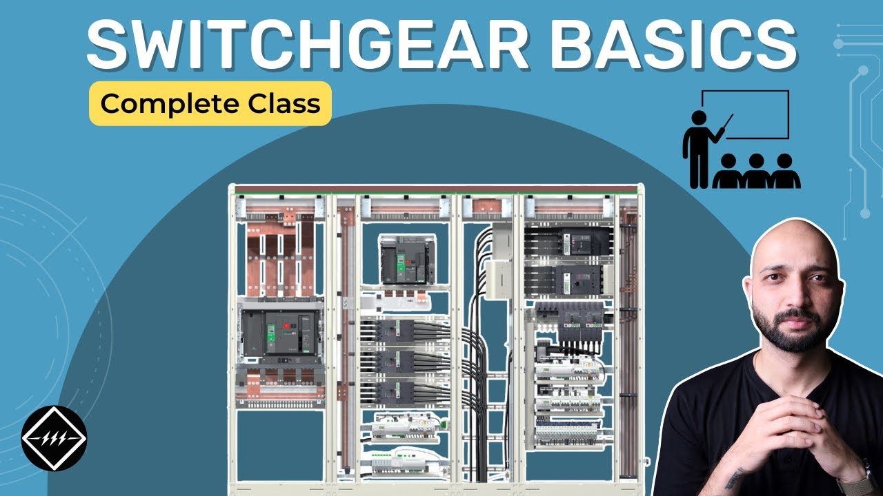
Gaurav J – TheElectricalGuy — Switchgear Basics: Complete Beginner’s Guide | TheElectricalGuy. This independent educational video provides background principles; it does not specify LBAJI equipment ratings or replace a project procedure.