Custom electric switchgear is an assembly configured for a particular electrical system, installation space and operating philosophy. Customization can involve bay functions, bus sections, protection, metering, auxiliary power, cable interfaces and controls. It does not mean the supplier can combine any components without checking the resulting design. A useful specification connects every requested feature to a project need and defines how the final assembly will be verified. This guide focuses on preparing and reviewing a custom order, including the design inputs, drawing approvals, change control and test evidence needed before the equipment is released for shipment.
Decide which requirements truly need customization
Start by comparing the project needs with available standard configurations. A standard lineup with documented options may solve the problem more clearly than a heavily modified enclosure. Separate electrical requirements from layout preferences and commercial requests. A required source-transfer function, a restricted cable entry and a preferred meter brand should appear as different items with different approval consequences.
Document the reason for each custom feature. A special feeder arrangement might support a critical process; a revised cabinet dimension might fit a constrained room. Identify whether the request affects ratings, insulation, cooling, service access or certification scope. Customization should make the system fit its intended duty, not merely make the quotation look distinctive. Ask the supplier to explain which features remain within its established design and which need additional assessment.

Prepare the electrical system inputs
Provide the nominal voltage, frequency, earthing arrangement, load schedule, prospective fault duty and source configurations. Identify utility, generator and other sources, including permitted parallel states. Share the single-line diagram and relevant study requirements. If a value is not yet known, record it as unresolved and agree how it will be established. Do not let the supplier’s default assumption become an approved project requirement without review.
Specify the functions of each bay and the required protection and metering interfaces. Continuous current and fault-breaking duty are different requirements. Device ratings and assembly withstand evidence need their own checks. For an LBAJI KYN28A-12-based discussion, request the actual proposed assembly configuration rather than extrapolating from the product photograph. A familiar product name does not define all custom options or establish their combined performance.
Define source transfer and interlocking behavior
Write an operating-state narrative showing normal supply, maintenance configurations and failure responses. State which breakers may be closed together and whether automatic transfer is included. If a tie is normally open, say so explicitly. Identify what happens when a source fails, a signal is unavailable or control power is lost. The supplier can then translate the approved narrative into a logic scheme that the buyer can review.
Do not rely on the single word “interlock.” Describe the prohibited operation and the conditions needed to permit it. Distinguish mechanical interlocks, hardwired electrical logic and software functions. Clarify local and remote control, test positions and manual recovery. Any synchronism, generator or utility interface requirements need responsible engineering approval. Factory tests should demonstrate the agreed logic under defined simulated conditions and identify what remains to be checked at the site.
Review layout and cable interfaces together
Provide equipment room dimensions, access paths, mounting provisions, cable routing and maintenance needs. Ask for a general arrangement that includes shipping sections and the actual ordered options. A reduced cabinet width may change cable termination space or access to components. Avoid approving the external dimensions without checking those internal and installation consequences.
Confirm top or bottom cable entry, cable sizes and quantities, termination responsibilities and external interface locations. Define whether bus duct, transformer connections or adjacent equipment are included. Ask how shipping sections are joined and what parts are supplied separately. Reconcile the arrangement with the construction drawings before release. Field cutting or unapproved rearrangement can create issues that were absent from the original verified design.

Specify protection and communications without ambiguity
Identify protection functions, instrument transformer interfaces, trip circuits and the owner of setting calculations. A particular relay model does not define its settings or complete integration. Request the proposed configuration, auxiliary supply and testing boundaries. For external contacts, specify signal type, state meaning and terminal identification. Each interface should have an owner on both sides of the cabinet boundary.
For communications, define protocols, point lists, units, scaling, alarms and commands. Clarify whether gateways, network equipment and integration services are included. A protocol name alone does not establish compatibility with the owner’s monitoring system. Agree the acceptance test and responsibility for configuration. Record the final settings and software versions so future maintenance can recover the accepted behavior rather than reconstruct it from a sales description.
Resolve the verification and certification route early
The required assembly standard and acceptance route depend on the equipment class, project and jurisdiction. UL’s information on switchboard programs illustrates that custom assemblies can operate within defined design and quality-control parameters. It does not establish that every custom cabinet or component combination is covered. Ask which evidence applies to the exact proposed design and which modifications require additional review or testing.
For a U.S. installation, coordinate with the responsible engineer and authority having jurisdiction. A field evaluation may be a relevant route for certain equipment, but it has its own scope and process. Define who arranges it, what it costs, when it occurs and who resolves any findings. Do not treat a planned evaluation as an existing approval. For other markets, specify the applicable requirements and retain matching evidence rather than combining unrelated standard claims.
Build a controlled approval package
The supplier should submit the single-line, general arrangement, component schedule, schematics, terminal drawings and relevant verification documents. Use a consistent revision system and identify approval status. Review documents as a connected set: a change in the one-line may affect protection logic, wiring and labels. Resolve comments before production reaches the affected stage.
Record deviations in a dedicated schedule. Each deviation should state the requested requirement, proposed alternative, reason and technical or commercial consequences. Silence in a drawing is not acceptance of a contractual deviation. Establish who may approve changes and what happens if the supplier discovers a conflict. A clear approval package helps both parties avoid building equipment that meets one drawing while violating another agreed requirement.

Manage substitutions and late changes
Component shortages and site changes can occur after the initial approval. Require a formal change request identifying affected parts, ratings, interfaces, drawings and verification scope. Ask whether the change modifies lead time, cost or warranty conditions. The engineering review should precede implementation. A replacement described as “equivalent” still needs evidence appropriate to its role in the assembly.
Define how accepted changes flow into the bill of materials, drawings, test procedure and handover file. Consider whether previous checks need repeating. A revised relay may change wiring and communications even if the primary circuit remains the same. A dimensional alteration may affect shipping and installation. The change record should help a future maintainer understand what was supplied and why, rather than preserve only an email conversation.
Agree factory tests and handover responsibilities
Prepare a test plan that distinguishes design evidence, routine production checks and project-specific functions. Include the operating sequences and interfaces created by customization. Define simulated inputs, expected outcomes, instruments, witnesses and the process for closing findings. Factory tests should not claim to prove site conditions that the setup cannot reproduce.
The final package should connect equipment serial numbers with as-built drawings, component records, accepted deviations and test results. Identify site commissioning activities, protection-setting approval and training responsibilities. Keep any unresolved item visible with an owner and closure condition. For electrical work, follow applicable safety rules and qualified procedures. OSHA provides useful U.S. work-practice context; it does not replace the site’s engineered isolation and commissioning process.
Custom order decision table
| Requested feature | Evidence needed before release | Common omission |
|---|---|---|
| Special bay arrangement | Approved one-line, ratings and arrangement | Bay functions disagree between documents |
| Automatic source transfer | Operating narrative and tested logic | Loss of control power is not addressed |
| Restricted installation space | Cable and maintenance-access review | Only external dimensions are checked |
| Remote monitoring or control | Point list, scaling and interface ownership | Protocol name is treated as complete integration |
| Component substitution | Accepted change request and scope review | Availability is mistaken for equivalence |
| Custom assembly acceptance | Matching verification or evaluation route | Component certification is used as assembly proof |
Häufig gestellte Fragen
Does custom switchgear always cost more?
Additional engineering, verification or special components can increase cost, but the outcome depends on the actual scope. A standard platform with approved options may meet the need efficiently. Request a quotation separating the base assembly, custom features, testing and service. Compare the final delivered function rather than assuming that the word “custom” implies either a premium or a saving.
Can I request any cabinet dimensions?
The supplier needs to assess the consequences for insulation, component arrangement, heat management, cable termination and maintenance access. A dimension that fits the room may not produce a suitable assembly. Provide the installation constraints and ask for an engineered arrangement. Keep the acceptance and verification implications visible before approving a reduced or altered enclosure.
Who should approve protection settings?
The contract should name the responsible engineer and define the study scope. The manufacturer may supply relays and standard functions while another party performs system coordination and approves settings. Record that boundary and require final configuration files. An installed relay or a factory functional check does not alone demonstrate that the system-level settings have been approved.
Can a factory test prove automatic transfer will work at the site?
It can demonstrate agreed logic using defined conditions, but actual sources, communications and installation interfaces may differ. The procedure should identify simulated elements and remaining site tests. Plan integrated commissioning separately and retain the accepted operating narrative. Avoid describing a factory simulation as proof of every real source-failure condition.
What should I request before placing the order?
Request a clear scope, assumptions, deviations, drawing list, approval milestones and verification route. Include the layout, cable interfaces, controls, tests and handover requirements. Define change approval and responsibility for site integration. The goal is an order that both parties can review against the same requirements, with unresolved inputs named before production begins.
Related LBAJI resources
LBAJI KYN28A-12 Metal-clad Withdrawable AC Switchgear. switchgear fundamentals. Testleitfaden für Schaltanlagen. switchgear maintenance checklist.
Technical sources
Use these references for the relevant equipment and work-practice scope. Confirm the edition and project requirements with the responsible engineer.
- IEC metal-enclosed AC switchgear scope
- OSHA electrical work practices
- UL switchboard certification program
Further viewing
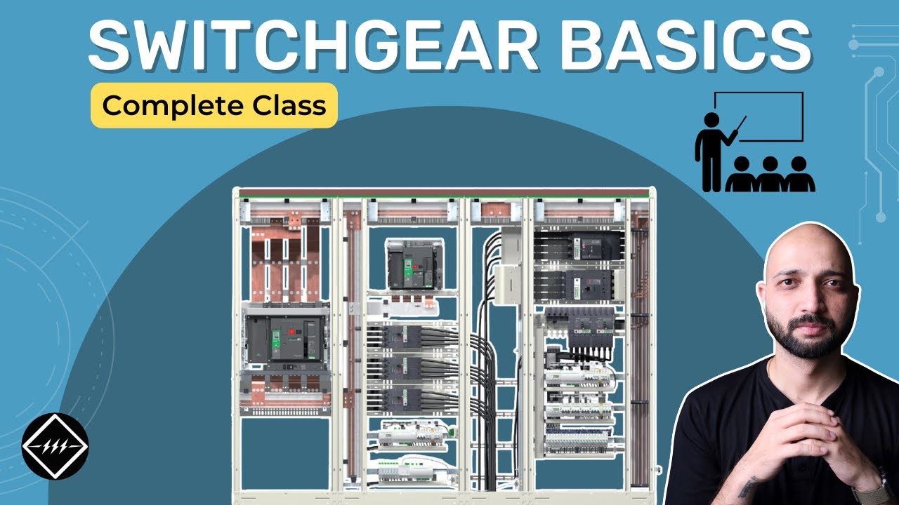
Gaurav J – TheElectricalGuy — Switchgear Basics: Complete Beginner’s Guide | TheElectricalGuy. This independent educational video provides background principles; it does not specify LBAJI equipment ratings or replace a project procedure.