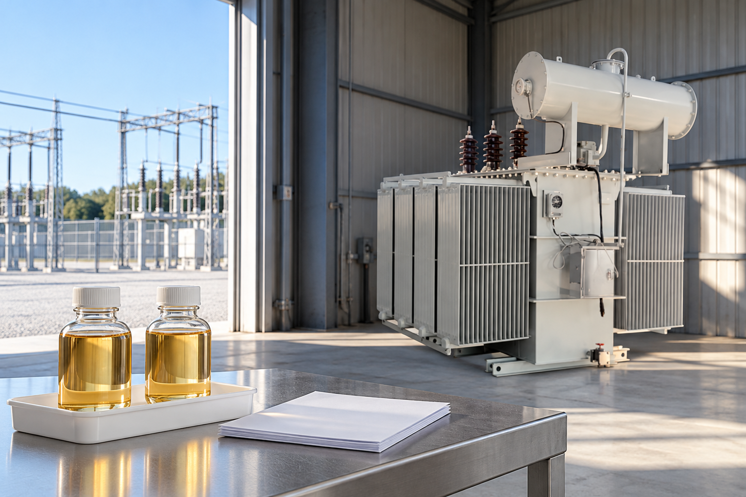
A transformer winding resistance test measures the DC resistance of an identified winding circuit to help assess conducting paths, connections and tap contacts. A useful result includes the winding and terminal arrangement, tap position, measurement temperature, instrument details and a suitable comparison baseline. The number alone cannot establish transformer condition. For buyers and maintenance engineers, the main task is to verify that the report compares equivalent circuits under compatible conditions, explains unusual readings and records the disposition of any exception before the transformer is accepted or returned to service.
What the test can tell a project team
Resistance testing addresses the current-carrying path. An unexpectedly high result can prompt investigation of connections, conductor continuity or tap contacts, but it does not identify the location of a defect by itself. The test belongs within a broader diagnostic assessment. Oil analysis, ratio measurements, operating history and other electrical tests answer different questions and can help determine whether an unusual resistance result deserves further investigation.
Le Bureau of Reclamation maintenance manual discusses winding resistance as a field diagnostic tool and emphasizes comparison with suitable previous or factory measurements. Its guidance is historical background, published in 2005, rather than a substitute for the current purchase specification or approved test method. A project should identify its governing documents before a contractor begins work, especially when different factory and site teams will prepare the records.
Confirm the winding circuit before comparing numbers
A terminal measurement is not automatically the resistance of one physical phase winding. The relationship depends on how the winding is connected and which terminals are accessible. Delta and star circuits can produce different terminal-to-terminal combinations. Internal parallel paths and externally connected equipment can further complicate interpretation. A report that simply lists three values without its connection basis leaves the reviewer unable to distinguish a circuit difference from a possible change in condition.
Ask for terminal designations that match the approved drawing, the winding connection and a record of the actual measurement arrangement. Where values have been converted into another representation, the calculation should be explained. Do not compare a derived phase value from one report directly with a terminal-pair value from another. Refer an uncertain conversion to the transformer manufacturer or responsible test engineer instead of assuming that a similar-looking number is equivalent.
Record the tap position and the condition as found
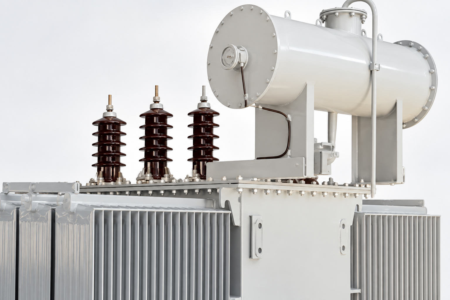
A tap selection can change the conducting path included in a resistance measurement. Consequently, a tap designation is part of the identity of the result. The test schedule should distinguish the initial operating position from additional positions covered by the approved scope. Recording only a final tap position can erase useful information about the condition in which the transformer arrived or had been operating.
The team should agree how tap positions will be named across the nameplate, operating mechanism, factory report and site worksheet. A number such as position three is insufficient if different documents count from opposite ends. Record the corresponding rated voltage or drawing reference where available. This is a documentation requirement, not permission to operate a tap changer: the equipment-specific instructions and safe working arrangements determine who may change it and under what conditions.
Why temperature changes the comparison
Winding conductor resistance varies with temperature. A warmer reading can therefore exceed an older cooler reading without indicating deterioration. A meaningful factory-to-site comparison needs either comparable thermal conditions or an approved correction to a common reference temperature. The material of the conductor matters to that correction, so a reviewer should not select a copper or aluminum constant from the transformer appearance or an assumed product family.
Where the adopted method uses the conventional linear temperature correction, its form is Rref = Rmeas × (K + Tref) / (K + Tmeas). Resistance values must use the same unit, Tref and Tmeas are temperatures in degrees Celsius, and K is the conductor-specific constant specified by the governing method. This equation adjusts the comparison basis; it does not compensate for an unstable reading, an incorrect circuit or an unreliable temperature estimate.
For an arithmetic illustration only, suppose the approved method supplies K = 234.5 °C for a copper winding. A measured resistance of 1.000 ohm at 25 °C, referred to 75 °C, becomes 1.000 × 309.5 / 259.5 = approximately 1.193 ohms. These are invented calculation inputs, not LBAJI test results or an acceptance criterion. A report should retain both the measured and corrected values so the reviewer can reproduce the arithmetic without losing the original observation.
Select a defensible temperature record
The temperature of surrounding air does not necessarily represent average winding temperature. A recently de-energized transformer can retain thermal gradients, and the top oil reading may differ from the average conductor temperature. The approved method should describe the thermal condition required for comparison and how the recorded temperature is obtained. A reviewer should question a worksheet that uses a convenient room-temperature entry without explaining why it represents the winding.
If reliable temperature information is unavailable, record that limitation and restrict the conclusion accordingly. It may still be possible for a competent engineer to assess compatible phase measurements collected under the same thermal conditions, but that does not automatically validate comparison with a factory reference at another temperature. Requesting a supported repeat measurement can be more useful than applying an elaborate correction to an uncertain input.
Review the instrument and the stability record
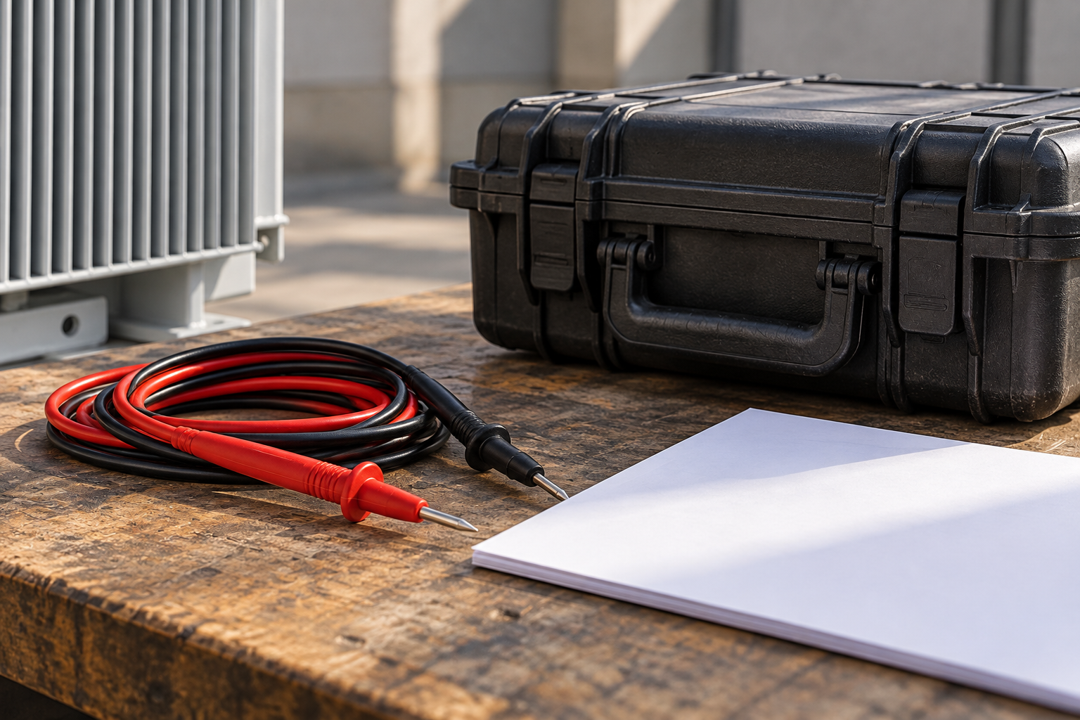
The test equipment must suit the resistance range and the equipment under test. Low resistance measurements are sensitive to the measurement arrangement and the distinction between current injection and voltage sensing. Instrument identification, calibration status, lead arrangement and the adopted method help a reviewer understand what the reported result actually represents. The NPTEL transformer-testing notes provide educational background on winding resistance measurement; the current instrument instructions govern the specific equipment used.
An inductive winding does not behave like an ordinary isolated resistor during every stage of a DC test. The operator must allow the instrument and winding response to meet the approved stability requirements. A saved final value without an explanation of stability may conceal a transient reading. Ask the contractor to identify how stabilization was recognized, whether automatic averaging was used and whether interruptions or connection changes occurred. Avoid inventing a universal test current or waiting time for every transformer.
Report review checklist
The following qualitative checklist organizes project evidence. It is a purchasing and review aid, not a test procedure or a list of standard acceptance limits.
| Élément à examiner | Documents à demander | Why the result may need clarification |
|---|---|---|
| Asset and winding | Serial number, winding identity and drawing reference | Similar transformer names can conceal different circuits |
| Terminals and connection | Terminal labels and measurement arrangement | Terminal-pair and phase values may be different quantities |
| Tap position | As-found position and each tested position | A changed path can change the resistance |
| Temperature | Measured basis and common reference temperature | Thermal differences can distort a trend |
| Instrument | Identity, calibration status and stable-reading record | An unexplained transient is a weak comparison |
| Assessment | Baseline, adopted criterion and exception disposition | A numerical difference is not a complete diagnosis |
Compare phases and historical records carefully
Start by asking whether the measurements are comparable at all. Review connection, tap position, temperature basis and instrument method before calculating a deviation. A common comparison expression is percentage change = 100 × (new value − baseline value) / baseline value, with both values expressed in the same units and on the same basis. The baseline must be nonzero and meaningful; a percentage computed from an unsuitable reference adds precision without adding reliability.
If a corrected historical value is 1.200 ohms and a compatible new corrected value is 1.212 ohms, the arithmetic change is +1.0%. This hypothetical example demonstrates the calculation only. Whether that change is acceptable depends on the adopted method, uncertainty, transformer design and relevant supporting evidence. Do not turn the example into a universal limit. Phase comparisons also require knowledge of the expected circuit relationship; equal terminal readings are not an appropriate assumption for every design.
Coordinate the order of diagnostic tests
DC testing can leave residual magnetism in the core. That can affect subsequent magnetically sensitive measurements, including excitation current assessment. The test team should plan the sequence before connecting equipment and document any relevant DC work performed earlier in the outage. Where demagnetization is required by the approved procedure, its completion and subsequent test conditions should be recorded by the competent team.
HSE HSG85 explains the need for planned electrical safe working practices. Winding resistance testing requires equipment isolation, control of possible sources and management of the energy associated with the inductive circuit under an approved procedure. This article does not give lead-changing or discharge instructions. An ordinary multimeter continuity check is not an equivalent substitute for a properly scoped transformer diagnostic test.
Turn an unusual result into a documented decision
An unexpected resistance should lead to a controlled review rather than an immediate diagnosis of a damaged winding. First check transcription, units, terminal identity, tap designation and thermal correction. Then have the responsible test team assess measurement repeatability and any limitations of the setup. Preserve the original reading and the reason for any replacement result; removing an inconvenient value destroys the audit trail.
Where the result remains unexplained, agree the next diagnostic action with the manufacturer and asset owner. The action might involve repeat testing under controlled conditions, targeted inspection or comparison with complementary tests. The acceptance record should identify the person responsible, the evidence reviewed and the remaining restrictions. A report marked pending should stay pending until those actions are resolved; a generic statement that the transformer was tested is insufficient.
Specify the test when ordering a transformer
For the LBAJI 35kV oil-immersed transformer family, buyers should request a project-specific test package that identifies the actual ordered configuration. The product photograph supports equipment identification, but it does not establish winding material, tap arrangement, measured resistance or a factory result. Ask which factory records are supplied, which site comparisons are expected and how the manufacturer supports questions about terminal and temperature bases.
A useful inquiry includes the rated voltages, connection and tap requirements, applicable specification, planned witness scope, report format and any requirement to preserve raw readings. Agree how exceptions will be handled before shipment and before energization. Clear reporting requirements help the factory, commissioning contractor and owner work from the same evidence instead of producing several incompatible spreadsheets after the equipment arrives.
Foire aux questions
Is winding resistance the same as insulation resistance?
No. Winding resistance concerns the conducting path, while insulation resistance concerns leakage through insulation under a specified test. Their units, methods and diagnostic purposes differ.
Can results from different tap positions be compared directly?
Only when the comparison explicitly accounts for the winding path and the approved tap schedule. Identify the exact tested position before interpreting a difference.
Should every value be corrected to 75 degrees Celsius?
Use the reference temperature required by the adopted method and comparison record. Seventy-five degrees is not an automatic requirement for every project or transformer.
Does one high reading prove that the winding is damaged?
No. Confirm the circuit, tap, temperature, measurement stability and repeatability, then assess the result with the manufacturer and complementary evidence.
Related equipment and guides
- LBAJI 35kV oil-immersed power transformer
- Guide complet des fondamentaux des transformers
- Transformer Testing: Methods, Procedures & Test Checklist
- Essais de réception en usine pour les transformateurs de puissance : Liste de contrôle pour la présence de l'importateur
Technical references
- Bureau of Reclamation: Transformers, Basics, Maintenance and Diagnostics (2005; historical background)
- IIT Madras NPTEL Electrical Machines I: Testing of Transformers
- HSE HSG85: Electricity at work, safe working practices
Further learning: Practical transformer modelling
This IIT Kharagpur NPTEL lecture explains modelling of a practical transformer, supporting the distinction between winding resistance and the other elements of the equivalent circuit. It is background theory, not a field winding-resistance procedure or acceptance criterion. Source: NPTEL IIT Kharagpur.