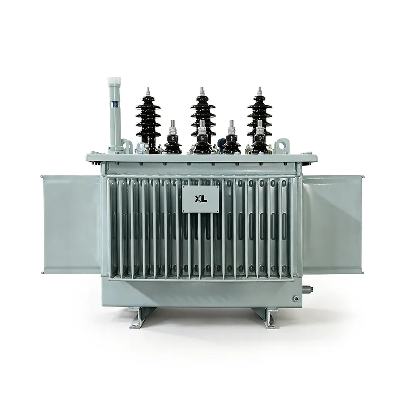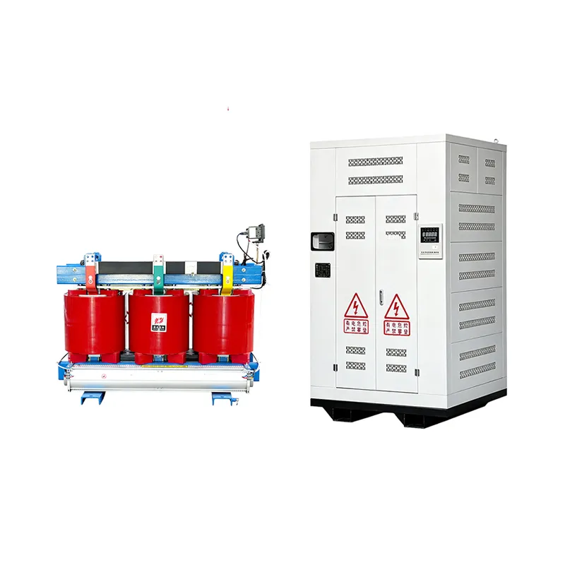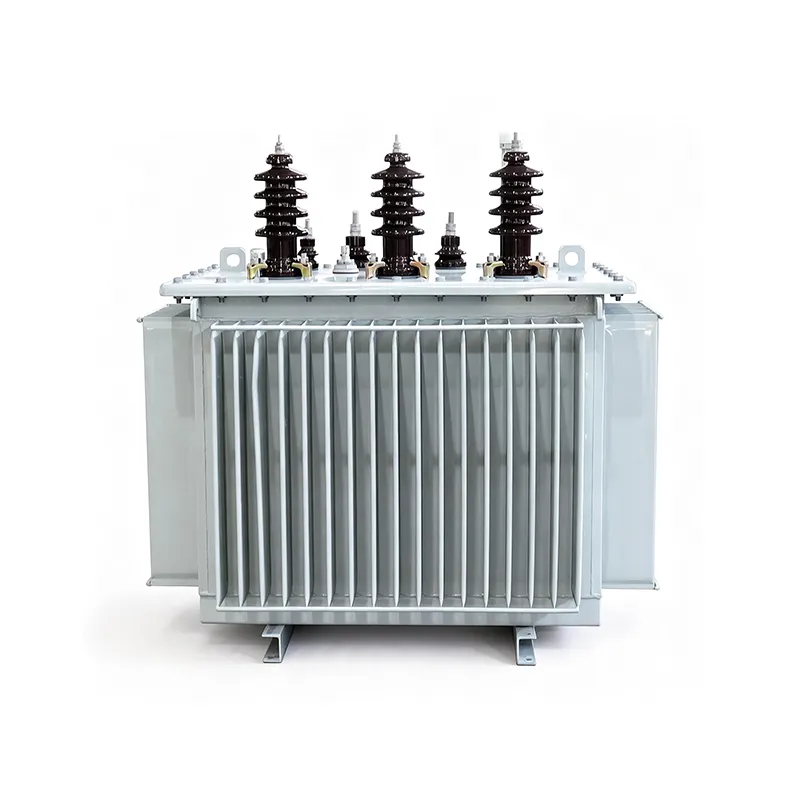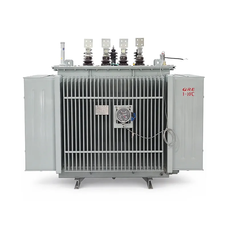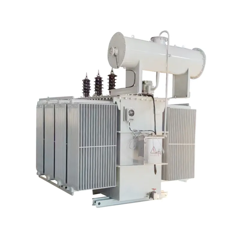
35 kV oil-immersed power transformers in the published S11 schedule cover three-phase ratings from 50 kVA to 40,000 kVA. The tables below separate the 50–630 kVA configurations from the 800–40,000 kVA configurations. They show reference voltage combinations, vector groups, no-load and load losses, no-load current and short-circuit impedance. Use the exact project model and approved manufacturer drawing to confirm the final values before procurement.
How to Read the 35 kV Transformer Tables
The smaller 50–630 kVA group lists a 35 kV high-voltage winding with a ±5% tap range, a 0.4 kV low-voltage winding and a Yyn0 vector group. The larger models list different secondary voltage options and Yd11; some models also list a 38.5 kV high-voltage option. These are distinct configurations, not interchangeable settings on one unit. Confirm voltage, frequency, tap arrangement and vector group against the approved single-line diagram.
The first table expresses loss figures in watts (W). The second table expresses its loss figures in kilowatts (kW): for example, 1.23 and 9.9 for the 800 kVA model. The former page labeled both tables in W, which made the larger-model values misleading. The numerical values below are preserved from the published schedule; request the signed technical data sheet for contractual or efficiency calculations.
What to Confirm Before Ordering
| Decision | Project information to provide | What the final data sheet should confirm |
|---|---|---|
| Electrical duty | Rated capacity, maximum demand, primary and secondary voltage, phase, frequency | Selected model, winding ratings and tap range |
| Network connection | Single-line diagram, neutral and earthing arrangement, upstream protection | Vector group, terminal arrangement and impedance |
| Losses and performance | Required efficiency evaluation and operating load profile | Guaranteed no-load and load loss units, reference temperature and test method |
| Site conditions | Indoor or outdoor location, ambient temperature, altitude and available space | Cooling method, enclosure or tank arrangement, dimensions and mass |
| Acceptance | Applicable standards, required tests, certificates and delivery documents | Approved drawings, routine test report and final nameplate |
For replacement work, include photographs of the existing transformer nameplate, the oil containment and foundation area, bushing positions and cable or busbar connections. These details can determine whether a nominally similar kVA model actually fits. For new substations, confirm the transformer interface with the high-voltage switchgear and low-voltage distribution equipment before approving layout drawings.
Read our transformer sizes guide for capacity ranges and the transformer sizing guide for load calculations. Send the project data through the contact page to request a matching technical schedule.
Download a Project RFQ Worksheet
For a structured inquiry, download the 35 kV oil-immersed transformer project specification and RFQ worksheet (PDF). It separates buyer requirements from supplier confirmations and is not a certified, model-specific datasheet.
50–630 kVA Reference Parameters
| Model | Rated Capacity (kVA) |
Rated Voltage(kV) | Vector Group |
Loss(W) | No-Load Current(%) |
Short Circuit Impedance(%) |
||
| High Voltage(kV) | Low Voltage(kV) | No-Load Loss |
Load Loss |
|||||
| S11-50/35 | 50 | 35±5% | 0.4 | Yyn0 | 210 | 1210 | 1.8 | 6.5 |
| S11-100/35 | 100 | 290 | 2020 | 1.62 | ||||
| S11-125/35 | 125 | 340 | 2380 | 1.56 | ||||
| S11-160/35 | 160 | 360 | 2830 | 1.48 | ||||
| S11-200/35 | 200 | 430 | 3300 | 1.39 | ||||
| S11-250/35 | 250 | 510 | 3960 | 1.26 | ||||
| S11-315/35 | 315 | 610 | 4760 | 1.26 | ||||
| S11-400/35 | 400 | 733 | 5760 | 1.16 | ||||
| S11-500/35 | 500 | 860 | 6900 | 1.16 | ||||
| S11-630/35 | 630 | 1040 | 8280 | 1.1 | ||||
800–40,000 kVA Reference Parameters
| Model | Rated Capacity (kVA) |
Rated Voltage(kV) | Vector Group |
Loss(kW) | No-Load Current(%) |
Short Circuit Impedance(%) |
||
| High Voltage(kV) | Low Voltage(kV) | No-Load Loss |
Load Loss |
|||||
| S11-800/35 | 800 | 35±5% | 10.5 6.3 3.15 |
Yd11 | 1.23 | 9.9 | 0.9 | 6.5 |
| S11-1000/35 | 1000 | 1.44 | 12.1 | 0.9 | 6.5 | |||
| S11-1250/35 | 1250 | 1.76 | 14.6 | 0.81 | 6.5 | |||
| S11-1600/35 | 1600 | 2.12 | 17.5 | 0.76 | 6.5 | |||
| S11-2000/35 | 2000 | 2.72 | 17.8 | 0.67 | 6.5 | |||
| S11-2500/35 | 2500 | 3.2 | 20.7 | 0.67 | 6.5 | |||
| S11-3150/35 | 3150 | 35±5% 38.5±5% |
3.8 | 24.3 | 0.63 | 7.0 | ||
| S11-4000/35 | 4000 | 4.52 | 28.8 | 0.63 | 7.0 | |||
| S11-5000/35 | 5000 | 5.4 | 33 | 0.54 | 7.0 | |||
| S11-6300/35 | 6300 | 35±2×2.5% 38.5±2×2.5% |
11 10.5 6.6 6.3 3.3 3.15 |
Yd11 | 6.56 | 36.9 | 0.54 | 7.5 |
| S11-8000/35 | 8000 | 9.0 | 40.5 | 0.49 | 7.5 | |||
| S11-10000/35 | 10000 | 10.88 | 47.7 | 0.49 | 7.5 | |||
| S11-12500/35 | 12500 | 12.6 | 56.7 | 0.45 | 8 | |||
| S11-16000/35 | 16000 | 15.2 | 69.3 | 0.45 | 8 | |||
| S11-20000/35 | 20000 | 18 | 83.7 | 0.45 | 8 | |||
| S11-25000/35 | 25000 | 21.28 | 99 | 0.36 | 8 | |||
| S11-31500/35 | 31500 | 25.28 | 118.8 | 0.36 | 8 | |||
| S11-40000/35 | 40000 | 28.8 | 155.25 | 0.48 | 8 | |||
All listed values are reference data for model selection. Final dimensions, weights and electrical values must follow the approved project drawings and manufacturer data sheet.