An electrical cabinet air conditioner keeps control panels, drives, PLCs and protection equipment within their allowable temperature and humidity range. The unit is not selected by cabinet dimensions alone. Start with the heat generated inside the enclosure, the highest ambient temperature, the target internal temperature, the enclosure sealing level and the available power. A correctly sized cooler protects electronics; an oversized or poorly installed unit can create short cycling, condensation and unnecessary maintenance.
Why cabinet cooling is different
A sealed electrical cabinet cannot rely on a fan exchanging air with a dusty or humid plant. A closed-loop air conditioner transfers heat from the cabinet interior to the surrounding environment while keeping the internal air separate. A filter fan, air-to-air heat exchanger or chilled-water unit may be more suitable when the heat load and ambient conditions allow it. The choice depends on contamination, enclosure rating, noise, maintenance and energy use.
Begin with the heat from every device: variable-frequency drives, servo drives, power supplies, transformers, PLCs, contactors, relays, resistors and network equipment. Add heat entering through the cabinet walls and doors. If the cabinet is in direct sun or beside a furnace, include solar and radiant gains. Record the maximum ambient, not the comfortable average.
| Input | Design question | Evidence |
|---|---|---|
| Internal heat load | How many watts are dissipated at full process load? | Device data sheets and load profile |
| Ambient | What is the highest surrounding temperature? | Site measurement and climate design value |
| Target internal temperature | What range protects the hottest component? | Component manuals and panel specification |
| Enclosure rating | Must the cooler preserve IP or NEMA performance? | Cabinet drawing and certification |
| Power supply | What voltage, frequency and inrush are available? | Control-power schedule and nameplate |
Estimate the cooling capacity
Cooling capacity is commonly expressed in watts or BTU/h. Convert the internal heat load and environmental gains into the unit’s rated conditions, then add a design margin. A rough calculation that uses only the drive nameplate can miss the losses from power supplies, contactors and cable compartments. Use the manufacturer’s capacity curve at the actual ambient temperature, because a unit rated at 35 °C may deliver less capacity at 50 °C.
Do not confuse electrical input power with cooling output. A cabinet cooler consumes power and rejects more heat outside than it removes from inside. Check the coefficient of performance, maximum ambient, starting current and circuit protection. If the enclosure contains a high-loss drive, ask for the drive’s heat-dissipation value at the expected switching frequency and load.
Choose an enclosure-compatible design
The cooler must be mechanically compatible with the cabinet door or side wall, with sufficient clearance for airflow, drainage and service. The mounting cutout, gasket, fasteners and cable entry affect the enclosure rating. A cooler installed over a door seam can compromise sealing. Follow the installation drawing and verify that the cabinet structure can support vibration and weight.
Manage condensation
Cooling a humid cabinet below the dew point can produce water on components or inside the drain pan. Use a thermostat and humidity strategy appropriate to the site. Keep the drain path clear and route condensate away from terminals. Some units include an evaporator, heater or anti-condensation control; confirm its limits rather than assuming it works in every ambient condition.
Rapid temperature changes can be as damaging as high steady temperature. A panel that cools overnight and then heats quickly at startup may have condensation on busbars and control boards. Consider a panel heater, enclosure breather or controlled ventilation where the environmental study supports it. Never drill an unapproved hole in a rated enclosure to solve a drain problem.
Airflow and hot spots
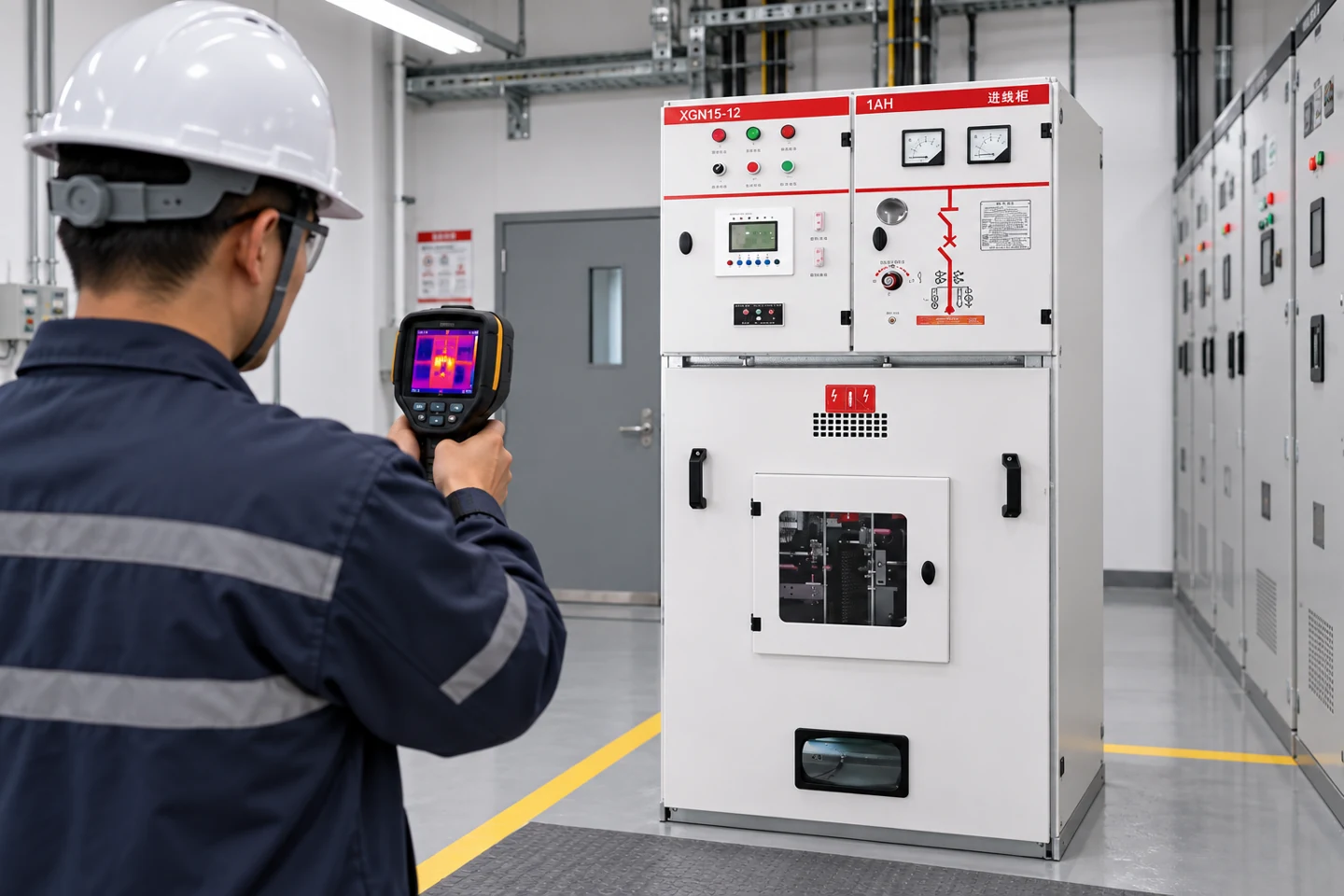
Internal airflow must reach the hottest devices. Keep a clear path around drives and power supplies, separate intake and exhaust, and install baffles when necessary. A cooler can show a normal outlet temperature while a drive heats because the air bypasses its heatsink. Use a thermal scan or calibrated sensors during commissioning to identify hot spots and verify the actual internal temperature.
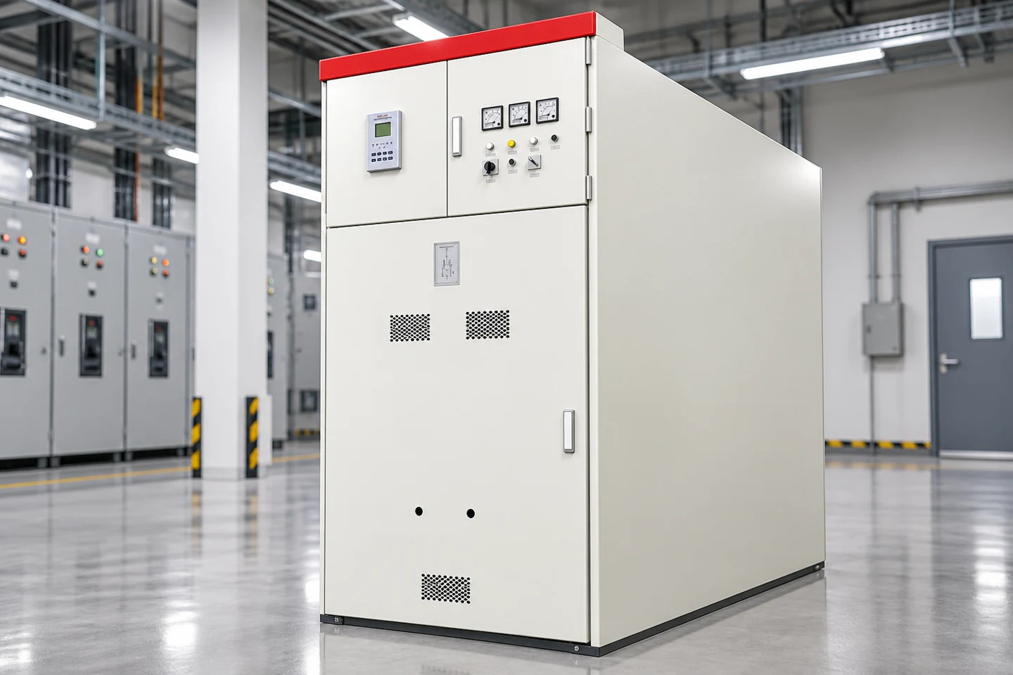
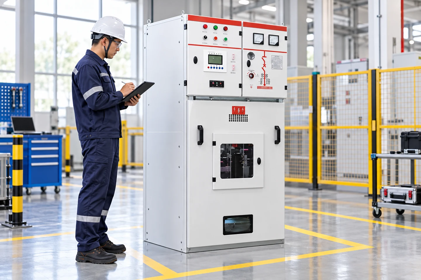
A withdrawable switchgear lineup may contain separate compartments with different losses and ventilation paths. The MNS/GCK/GCS switchgear page is a product reference for modular cabinet architecture. The final cooler selection must use the ordered enclosure drawing, compartment arrangement and heat-loss schedule.
Electrical and control requirements
Provide a dedicated protective device sized for the cooler’s running and starting current. Check the control voltage, frequency, phase, earthing, disconnect and auxiliary alarm contacts. A high-temperature alarm should be wired to the PLC, SCADA or local indicator so a failed cooler is noticed before equipment overheats. Some units provide door switches, filter alarms and compressor protection; map each signal in the control drawing.
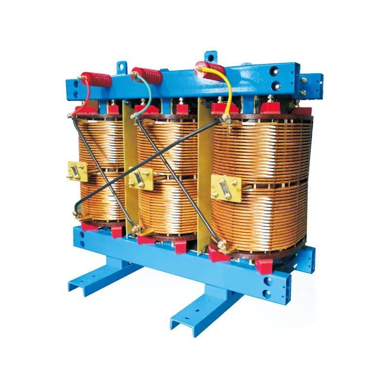
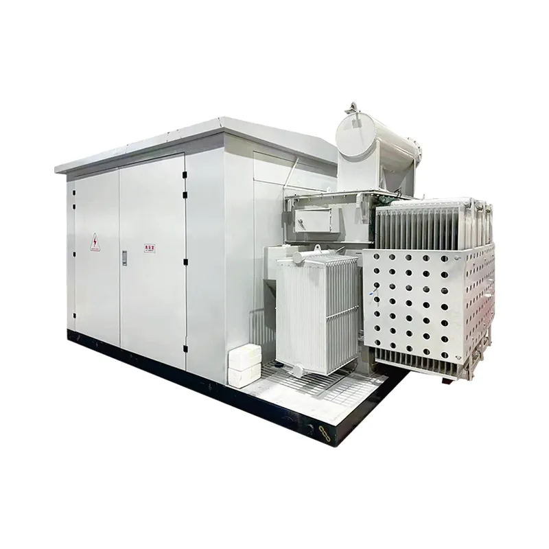
Keep the cooler’s power and control wiring separated from sensitive analog or communication cables. Confirm electromagnetic compatibility, cable gland sealing and the required short-circuit rating. If the cabinet is part of a packaged substation, coordinate the cooler with the auxiliary supply, transformer losses and outdoor ambient. The LBAJI YBM-12 substation is an external product reference; its image does not define an air-conditioning specification.
Outdoor and renewable-energy cabinets
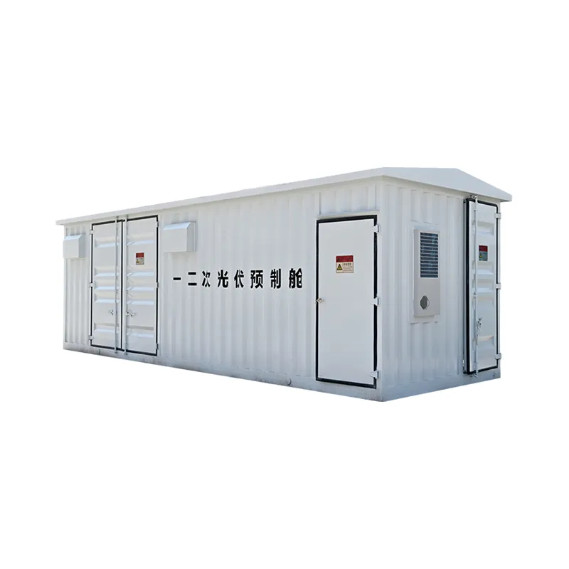
Outdoor photovoltaic and distribution cabinets face solar loading, rain, dust, salt, temperature cycling and limited maintenance access. Select a unit with an appropriate outdoor rating and corrosion protection. Verify that the cooler can reject heat at the worst ambient and that the cabinet foundation prevents water pooling. The BWG-800 grid-connected cabinet provides a product-family reference for renewable-energy equipment, but the installed inverter and protection schedule determine the heat load.
Filters and maintenance
Closed-loop coolers still require cleaning of condenser coils, fans, drains and seals. Dust on the condenser reduces heat rejection and raises compressor temperature. Keep a maintenance interval based on site contamination rather than a generic calendar. Check the drain, gasket, filter indicator, fan noise and compressor cycling. Record internal and ambient temperatures so performance decline is visible.
During maintenance, isolate the cooler according to its electrical procedure and allow stored energy and hot surfaces to reach a safe condition. Do not open refrigerant circuits without qualified service. Inspect the panel for corrosion or condensation before returning it to service. A cooler that runs continuously may indicate a failed gasket, blocked condenser, increased process load or an undersized selection.
Commissioning checks
Verify the cutout, gasket, fasteners, earth connection, drain, control settings and alarm contacts. Run the cabinet at representative process load and record internal temperature at the hottest component, ambient temperature, cooler current and compressor cycling. Test the high-temperature alarm and any door or filter alarm. Repeat the test after the cabinet reaches thermal equilibrium rather than relying on the first ten minutes.
Review the result against every component’s temperature limit. A cabinet may remain below the cooler setpoint while a drive or resistor exceeds its local rating. Use a thermal camera or installed sensor to check the actual component surfaces. Keep the commissioning record with the cabinet drawing and cooler model.
Sizing and procurement checklist
Ask for the cooling capacity curve, maximum ambient, power input, inrush current, enclosure compatibility, gasket detail, ingress rating, condensate behavior, alarm contacts, refrigerant and service requirements. Provide the supplier with the enclosure dimensions, heat-loss schedule, ambient profile, solar exposure, target temperature and cabinet rating. Request confirmation that the selected model preserves the enclosure’s tested construction.
Finally, plan for failure. Define the alarm response, spare availability, temporary ventilation method and safe shutdown for critical equipment. Cooling is part of the electrical system’s reliability plan, not an accessory added after the panel is built.
Thermal design should also consider control-system reliability. Network switches, safety relays and analog input cards may have a narrower humidity or temperature range than the main power devices. Place temperature sensors near the most sensitive equipment and define the alarm threshold with enough time for an operator to respond. If the panel is redundant, verify that one failed cooler does not remove both control channels.
Where a cabinet contains batteries, capacitors or a UPS, review charging losses, venting and gas-management requirements separately. Cooling cannot be used to hide a ventilation or fire-protection issue. Coordinate the enclosure thermal calculation with the electrical, mechanical and fire-safety drawings before fabrication.
For a large lineup, consider zoning. One cooler may not provide uniform airflow through several sections, while multiple smaller units can improve redundancy but add penetrations and maintenance points. Use the supplier’s airflow and pressure data, then verify the final arrangement with a loaded thermal test. Preserve spare cutout plates so a failed unit can be isolated without leaving an open enclosure.
Document the cooler setpoint, high-temperature threshold and restart delay on the cabinet drawing. These values should be visible to operators and included in the commissioning record. A clear alarm and reset procedure is often more valuable than a lower nominal setpoint that causes repeated compressor cycling.