The power factor of a motor describes how effectively the motor converts apparent electrical power into real mechanical output. Induction motors normally have lagging power factor because their magnetic field requires reactive current. The value changes with load, voltage, speed, motor size, efficiency and starting method, so a nameplate or catalog value is not the same as the PF measured at every operating point.
What leading and lagging mean
In a sinusoidal circuit, current lags voltage when an inductive load stores energy in a magnetic field. Current leads voltage when a capacitive load stores energy in an electric field. Real power is measured in kW, reactive power in kvar and apparent power in kVA. The relationship is power factor = kW/kVA, while the sign of kvar or phase angle shows the direction.
| Observation | Likely condition | Check |
|---|---|---|
| Positive or importing kvar on an inductive load | Lagging power factor | Meter convention and phase-angle sign |
| Negative or exporting kvar with capacitors connected | Leading power factor | Capacitor status and CT polarity |
| PF near 1 but kvar changes sign | Transition between leading and lagging | Load and capacitor switching sequence |
| PF sign appears inconsistent | Possible CT/PT polarity or phase mapping error | Wiring diagram and phase test |
| Low PF during motor start | High reactive and transient current | Starting method and event record |
Use the meter’s reactive-power sign
Many power-quality meters display kW, kvar, kVA, PF and a lead/lag indication. Read the instrument manual because sign conventions differ. Some meters show positive kvar for lagging load and negative kvar for leading load; others use import/export language. Do not copy a sign rule from another instrument without checking its phase sequence and CT orientation.
Record the display while a known inductive load is operating, then connect or disconnect a verified capacitor stage and observe the change. If kvar moves toward zero, the capacitor is compensating the inductive load. If it crosses zero and becomes capacitive, the system has become leading at that operating point. Excessive leading operation can create overvoltage or resonance concerns.
Calculate from kW and kvar
If the meter provides signed kW and kvar, the apparent power magnitude is S = √(P² + Q²), and the power-factor magnitude is |PF| = |P|/S. The phase angle can be calculated as φ = atan2(Q, P), with the sign of Q indicating the chosen leading or lagging convention. Keep the signed values and the convention in the report instead of recording only the absolute PF.
For example, a load of 80 kW and +60 kvar has 100 kVA and PF 0.80 under a convention where positive kvar means lagging. If capacitor correction changes the reading to 80 kW and −20 kvar, the magnitude is about 82.5 kVA and PF about 0.97 leading. The sign change is the important result; the exact interpretation still follows the meter convention.
Check current waveform and phase angle
A power analyzer can display voltage and current waveforms and calculate phase angle for each phase. A lagging current waveform reaches its peak after the voltage reference; a leading waveform reaches it before the reference. Harmonics make a simple single-angle view incomplete, so review displacement power factor and true power factor separately when nonlinear loads are present.
Verify phase sequence, CT polarity, PT polarity and channel mapping. A reversed CT can make an inductive load look capacitive or create a negative kW reading. Compare the analyzer result with a known reference load and the one-line diagram. Never adjust a capacitor bank based on a sign that has not been validated.
Motor and transformer behavior
Induction motors normally operate with lagging displacement power factor, especially at light load and during starting. Transformers also draw magnetizing reactive power. The PF changes with load, voltage and control mode. A motor that appears acceptable at full load may be strongly lagging while lightly loaded. Record operating current, kW, kvar, voltage and speed together.
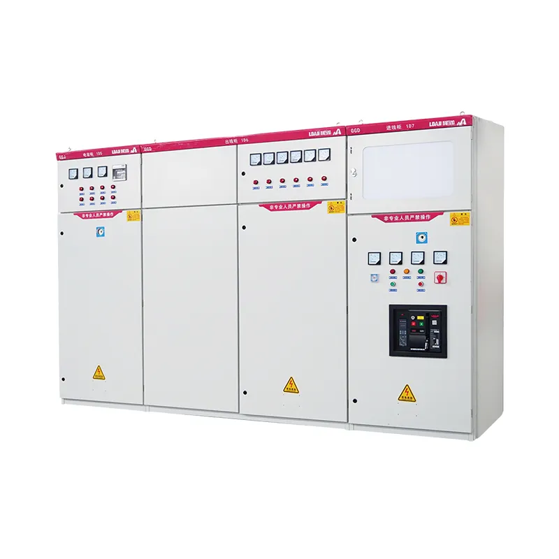
Variable-frequency drives can improve input displacement power factor while still producing current harmonics. A capacitor bank connected directly at a drive output is generally inappropriate. Review the drive manual, harmonic study and detuning requirements before adding correction equipment. The LBAJI GGD low-voltage switchgear page is a product reference for distribution; the actual PF equipment must be selected from the system study.
Capacitor banks and overcorrection
Automatic capacitor banks switch stages to follow load. If stages remain connected while motors are stopped, the system can become leading. Leading kvar may increase voltage, interact with transformers and excite resonance with network inductance. Use a controller with correct CT location, target PF, switching delay and discharge time. Confirm that each stage has fuses, contactors, reactors where required and safe discharge resistors.
Measure PF at the point specified by the utility or project requirement. A local panel may look near unity while the main incomer remains lagging because another feeder is not compensated. A capacitor bank can also correct one feeder while causing overcorrection at night or during low production. Trend readings over the full operating cycle.
Three-phase measurement
For a balanced three-phase system, use the analyzer’s three-phase method and correct line-to-line or line-to-neutral voltage settings. In an unbalanced system, inspect each phase’s kW, kvar, current and PF. A single total PF can hide a leading phase and a lagging phase. Check neutral current, phase sequence and the current-transformer ratio.
CT placement is important when loads include generators, PV inverters, transfer switches or multiple incomers. The CT must see the power flow that the controller is intended to regulate. A sign that changes when a transfer switch operates may be correct, or it may reveal that the CT is on the wrong side of the switch. Trace the current path on the single-line.
Commissioning and troubleshooting
Start with a known load and verify meter phase mapping. Record kW, kvar, kVA, PF, voltage, current, frequency and harmonics. Switch one capacitor stage or known inductive load at a time and confirm the expected sign change. If the reading is implausible, check CT polarity, PT wiring, phase sequence, scaling, grounding and firmware configuration before changing hardware.
When a PF controller hunts between stages, review delay, deadband, discharge time, CT location and minimum load. When PF is unexpectedly leading, inspect stuck contactors, welded stages, a lightly loaded transformer and inverter reactive-power settings. Do not disable protection or bypass a controller without an approved procedure.
Reporting
A useful report states the instrument model, calibration, wiring configuration, sign convention, sampling period, operating load, capacitor stages, kW, kvar, kVA, PF and harmonic values. Include screenshots or event records when the direction changes. The leading versus lagging comparison provides a basic terminology reference; the project report should retain the measured signs and assumptions.
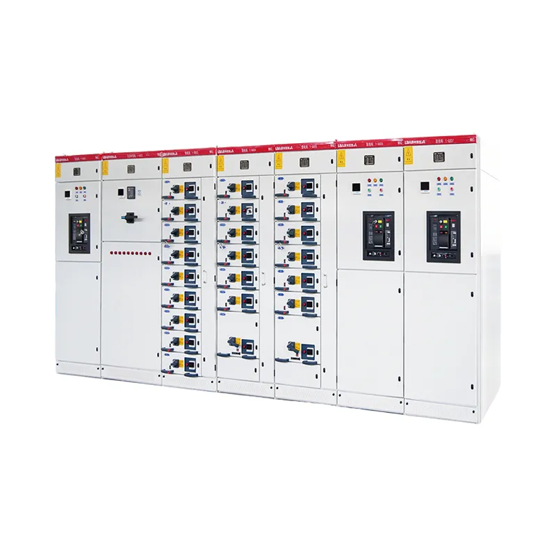
For renewable-energy installations, distinguish inverter reactive-power control from capacitor correction. The LBAJI BWG-800 cabinet is an equipment reference, not evidence of a particular PF setting. Confirm the inverter mode, grid code, transformer connection and utility requirement before changing the target.
Trend the sign and magnitude over a complete operating cycle. A factory can be lagging during production, near unity at peak load and leading during breaks when capacitor stages remain connected. Store interval data with the controller state so a sign change can be explained. A single spot reading is not enough to size or tune a correction system.
Check the measurement at both the feeder and the main incomer when the installation has multiple compensation points. A local capacitor bank can make its feeder look excellent while another feeder imports reactive power. The utility meter may see the net result at a different point. Mark the CT location and measurement boundary on the single-line diagram.
Harmonics can distort the current waveform so that displacement PF and true PF differ. A capacitor bank may resonate with the supply inductance at a harmonic frequency. Use a power-quality analyzer and a harmonic study before adding stages or changing reactors. Detuned banks, active filters or inverter controls may be more appropriate than a simple capacitor contactor.
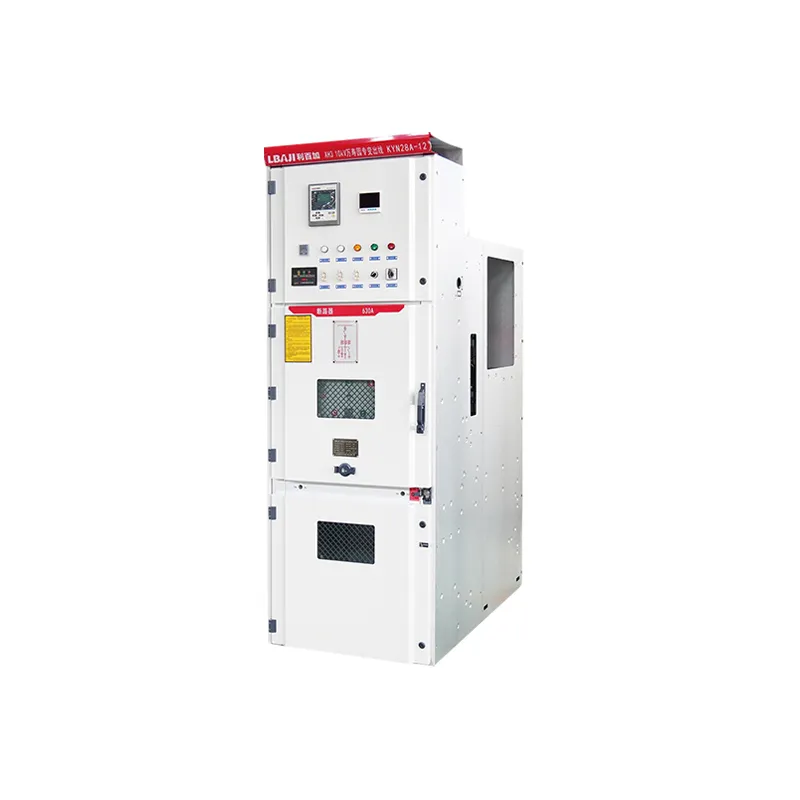
When a meter shows unexpected leading power factor, first verify CT polarity and phase mapping, then inspect capacitor contactors and inverter settings. Do not change the target PF until the sign convention and wiring have been proven with a known load. Document the correction, alarm thresholds and maintenance response in the commissioning file.
Finally, define an operating deadband so the controller does not switch capacitor stages for every small fluctuation. Include discharge time, minimum load and alarm limits in the control narrative. Review the target with the utility requirement and the equipment manufacturer’s limits rather than choosing the highest possible PF at every moment.
Record the target, deadband and alarm limits in the panel documentation so a future controller replacement does not change the lead/lag behavior unnoticed.
Motor-specific correction decisions
Correcting a motor’s lagging PF can reduce feeder current and transformer loading, but capacitor size must follow the real operating profile. Oversized correction can make the system leading when the motor is unloaded or disconnected. Do not connect a capacitor directly to a variable-frequency-drive output. Follow the drive manufacturer and harmonic study requirements.
For a motor starter, coordinate overload protection, contactor duty, capacitor switching and breaker settings. A capacitor bank may remain energized after the motor opens unless discharge and interlocking are designed correctly. Verify the CT location when an automatic PF controller is used.
Motor power factor also affects generator and transformer sizing. A generator must supply both real and reactive current, while a transformer experiences heating from apparent power. Include starting current and the worst operating PF in the source study.