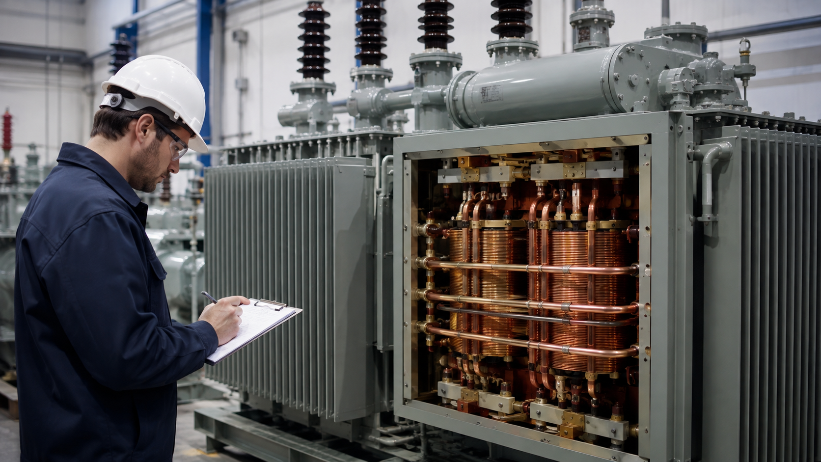
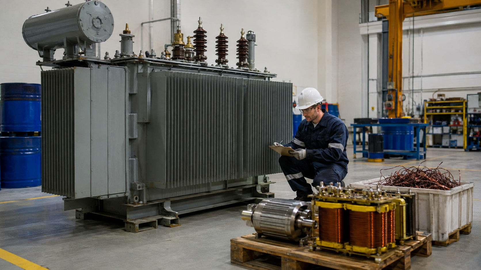
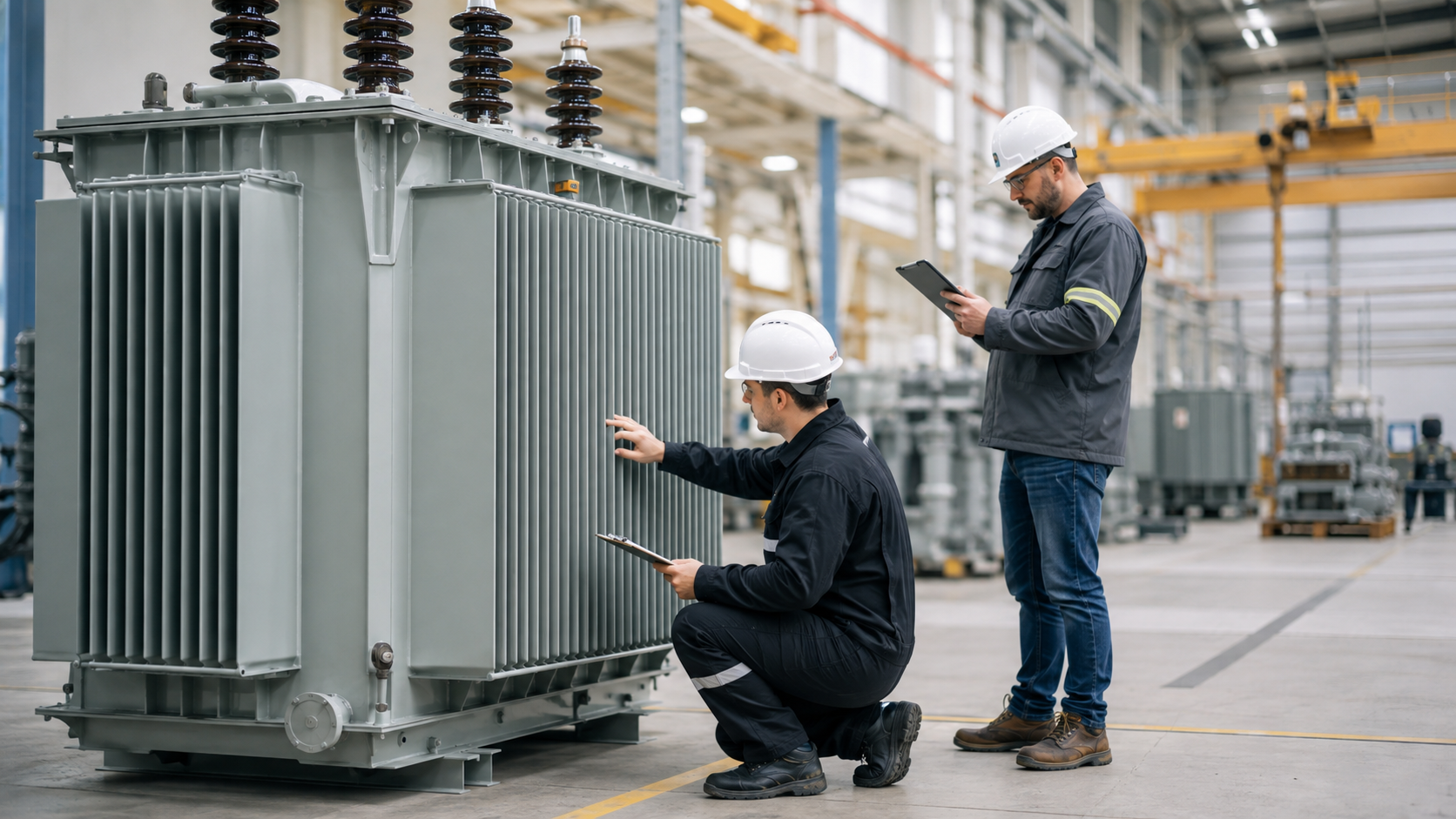
The transformer core creates a low-reluctance path for alternating magnetic flux, while windings transfer energy between voltage levels. A complete power transformer also needs insulation, tank, oil or air cooling, bushings, tap changing, monitoring and protection. This guide explains the main transformer components, their functions and the failure modes they are designed to control.
Transformer Core
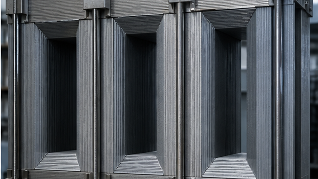
The core carries alternating magnetic flux linking primary and secondary windings. Power transformers commonly use grain-oriented electrical steel with high permeability and low specific loss. Thin sheets are coated with insulation and stacked to reduce eddy-current circulation.
Core joints are often step-lap arrangements that reduce local flux concentration, noise and loss. Limbs carry windings and yokes close the magnetic path. Clamps provide mechanical stability but require careful insulation and grounding to avoid circulating current.
Core Losses and Sound
No-load loss includes hysteresis and eddy-current loss and exists whenever rated voltage is applied. It depends on material, flux density, frequency, joints and manufacturing stress. Magnetostriction makes the core vibrate and contributes to transformer hum. Correct clamping and low-flux-density design help control sound.
Quick Comparison and Selection Table
Use this table as a quick review of the main engineering and procurement decisions explained in the article.
| Decision area | Practical meaning | What to verify |
|---|---|---|
| Transformer Core | The core carries alternating magnetic flux linking primary and secondary windings. | Power transformers commonly use grain-oriented electrical steel with high permeability and low specific loss. |
| Core Losses and Sound | No-load loss includes hysteresis and eddy-current loss and exists whenever rated voltage is applied. | It depends on material, flux density, frequency, joints and manufacturing stress. |
| Transformer Windings | Windings use copper or aluminum conductors arranged as layers, discs, helices or foil depending on voltage, current and short-circuit duty. | The lower-voltage winding is often placed nearer the core to simplify insulation, with the high-voltage winding outside, although design needs can vary. |
| Insulation System | Liquid-filled transformers use cellulose paper/pressboard with insulating liquid. | Dry-type units use resin, varnish, solid insulation and air. |
| Transformer Tank and Oil | The tank contains the active part and insulating liquid, provides mechanical protection and acts as a heat-transfer surface. | It must withstand vacuum, internal pressure, transport loads and seismic forces as specified. |
Transformer Windings
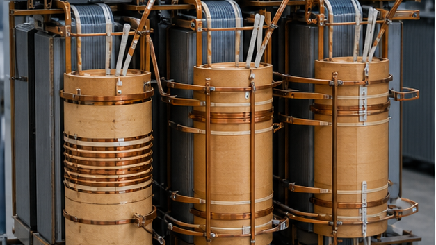
Windings use copper or aluminum conductors arranged as layers, discs, helices or foil depending on voltage, current and short-circuit duty. The lower-voltage winding is often placed nearer the core to simplify insulation, with the high-voltage winding outside, although design needs can vary.
Conductors may be transposed to reduce circulating and eddy losses. Axial and radial spacers create cooling ducts and support coils against electromagnetic forces during faults.
Insulation System
Liquid-filled transformers use cellulose paper/pressboard with insulating liquid. Dry-type units use resin, varnish, solid insulation and air. Insulation must withstand operating voltage, impulses, temperature, moisture and mechanical stress. Aging accelerates as winding hot-spot temperature and moisture rise.
Transformer Tank and Oil
The tank contains the active part and insulating liquid, provides mechanical protection and acts as a heat-transfer surface. It must withstand vacuum, internal pressure, transport loads and seismic forces as specified. Magnetic shunts may control stray flux in tank walls.
Mineral oil provides insulation and cooling. Alternative fluids may offer higher fire point or environmental benefits. Fluid quality is monitored through dielectric, moisture, acidity and dissolved-gas tests.
Cooling Equipment
Radiators increase surface area for heat rejection. Fans force air across radiators and pumps circulate oil in higher-rated cooling stages. Common designations describe oil/air circulation modes. Temperature sensors and controls start cooling groups and alarm or trip if limits are exceeded.
Conservator and Breather
A conservator accommodates oil expansion and contraction while keeping the main tank full. A bladder or diaphragm can reduce oil contact with air. A silica-gel breather dries air entering the conservator. Sealed-tank transformers instead accommodate pressure change within the tank design.
Bushings and Terminals
Bushings carry conductors through the grounded tank while maintaining insulation. Their design depends on voltage and current and may use porcelain, composite housings or capacitance-graded insulation. Correct creepage, connection torque, sealing and condition monitoring are critical.
Tap Changers
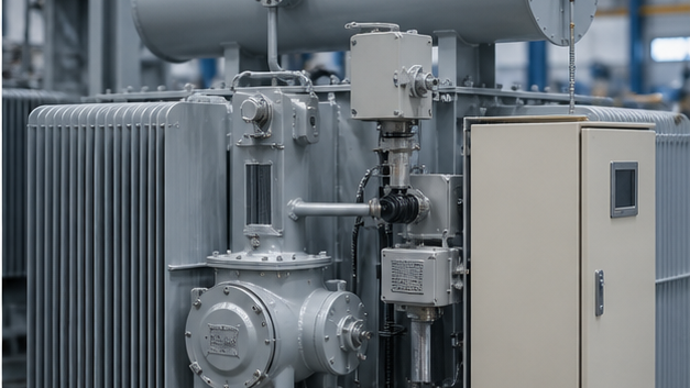
An off-circuit tap changer changes turns ratio only when de-energized. An on-load tap changer changes taps while carrying load using transition impedance to avoid interrupting current or shorting turns. OLTCs include diverter or selector mechanisms, drive, position indication and a control cabinet and need dedicated maintenance.
Protection and Monitoring Accessories
- Buchholz relay: detects gas accumulation and oil surge between tank and conservator.
- Pressure-relief device: relieves dangerous internal pressure.
- Oil and winding temperature indicators: alarm, trip and control cooling.
- Oil-level gauge: shows liquid level and abnormal conditions.
- Sudden-pressure relay: responds to rapid internal pressure change.
- Online monitors: may track dissolved gas, moisture, bushings or partial discharge.
Marshalling Cabinet
The marshalling cabinet gathers terminal blocks, cooling controls, heater, relays, indicators and interfaces to protection/SCADA. It should provide environmental sealing, anti-condensation, clear wiring and safe separation of circuits.
Core-and-Coil Assembly Quality
Manufacturing controls conductor tension, winding dimensions, drying, compression, lead support and contamination. Short-circuit forces can displace windings if mechanical design or clamping is inadequate. Factory tests verify resistance, ratio, vector group, losses, impedance and insulation performance.
Product Application
LBAJI’s 35 kV oil-immersed power transformer integrates these active and auxiliary components for project-specific ratings. It can be combined with KYN61-40.5 switchgear or packaged in a 35 kV new-energy substation.
Inspection Checklist
- Verify nameplate, drawings and accessory list.
- Inspect tank, radiators, bushings and seals.
- Check core/tank grounding and neutral connections.
- Test cooling groups, alarms and trips.
- Confirm tap-changer operation and position.
- Obtain baseline oil, electrical and protection results.
- Record torque, wiring and marshalling-cabinet checks.
Core-type, shell-type and amorphous cores
In a core-type transformer, windings surround core limbs; in a shell-type design, the magnetic circuit more fully surrounds the windings. Grain-oriented silicon steel is common at power frequency, while amorphous metal can reduce no-load loss. The choice affects loss, sound, mechanical strength, manufacturing and cost.
Copper versus aluminum windings
Either conductor can deliver reliable service when current density, joints, mechanical strength and thermal design are engineered correctly. Copper usually offers higher conductivity and compactness; aluminum reduces mass and material cost. Buyers should compare guaranteed loss, temperature rise and short-circuit performance rather than conductor name alone.
Technical references and further reading
The following independent sources support the standards, terminology, calculations, and safety context discussed in this guide:
- IEC 60076-1 power transformer standard — Scope, terminology, ratings, connection symbols, testing, safety, and general requirements for power transformers.
- U.S. Department of Energy: Distribution Transformers — Official definitions, efficiency requirements, test procedures, and regulatory resources for distribution transformers.
- OSHA electric power transmission and distribution requirements — Safety requirements relevant to construction and work around electric power transmission and distribution equipment.