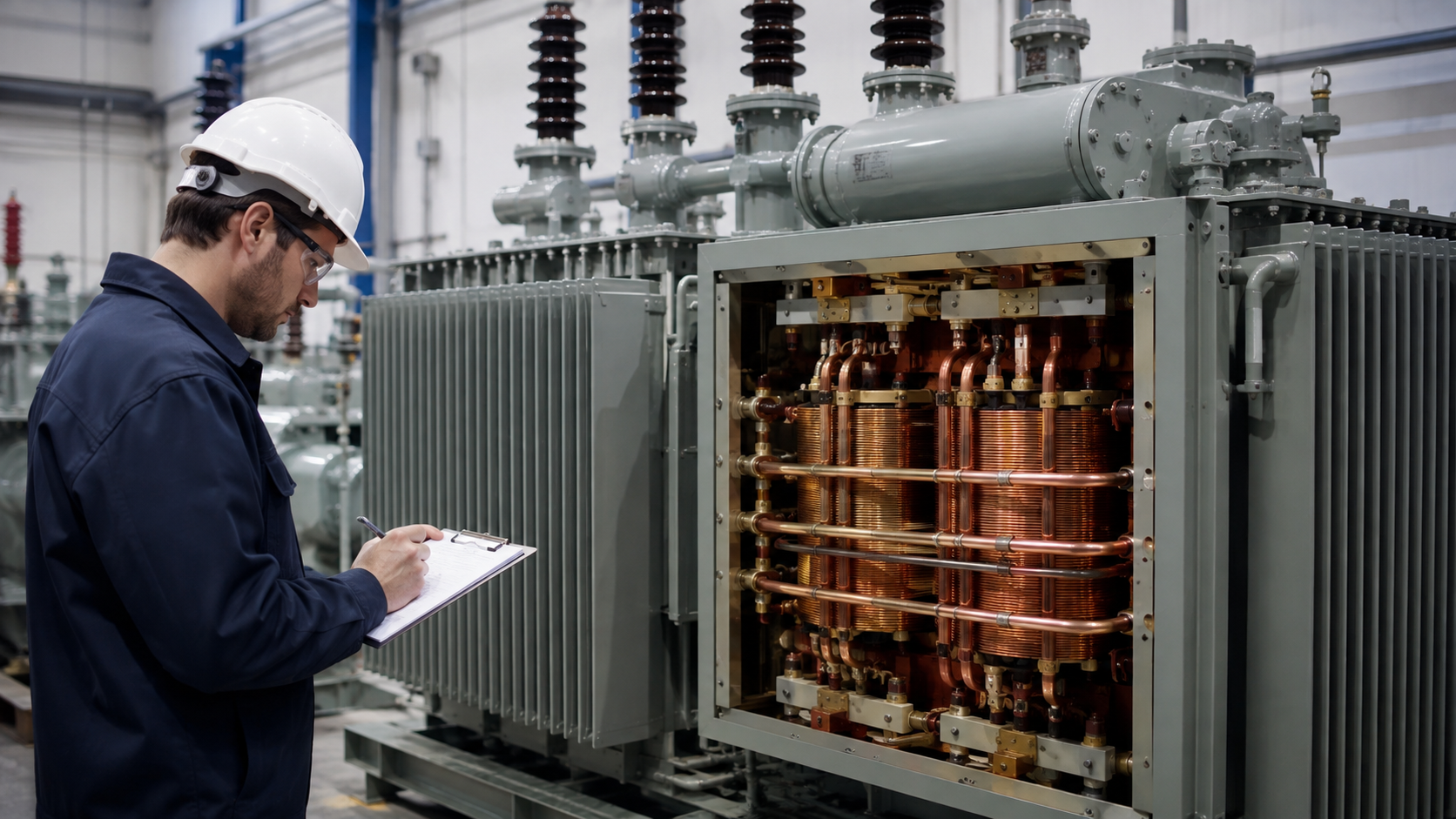
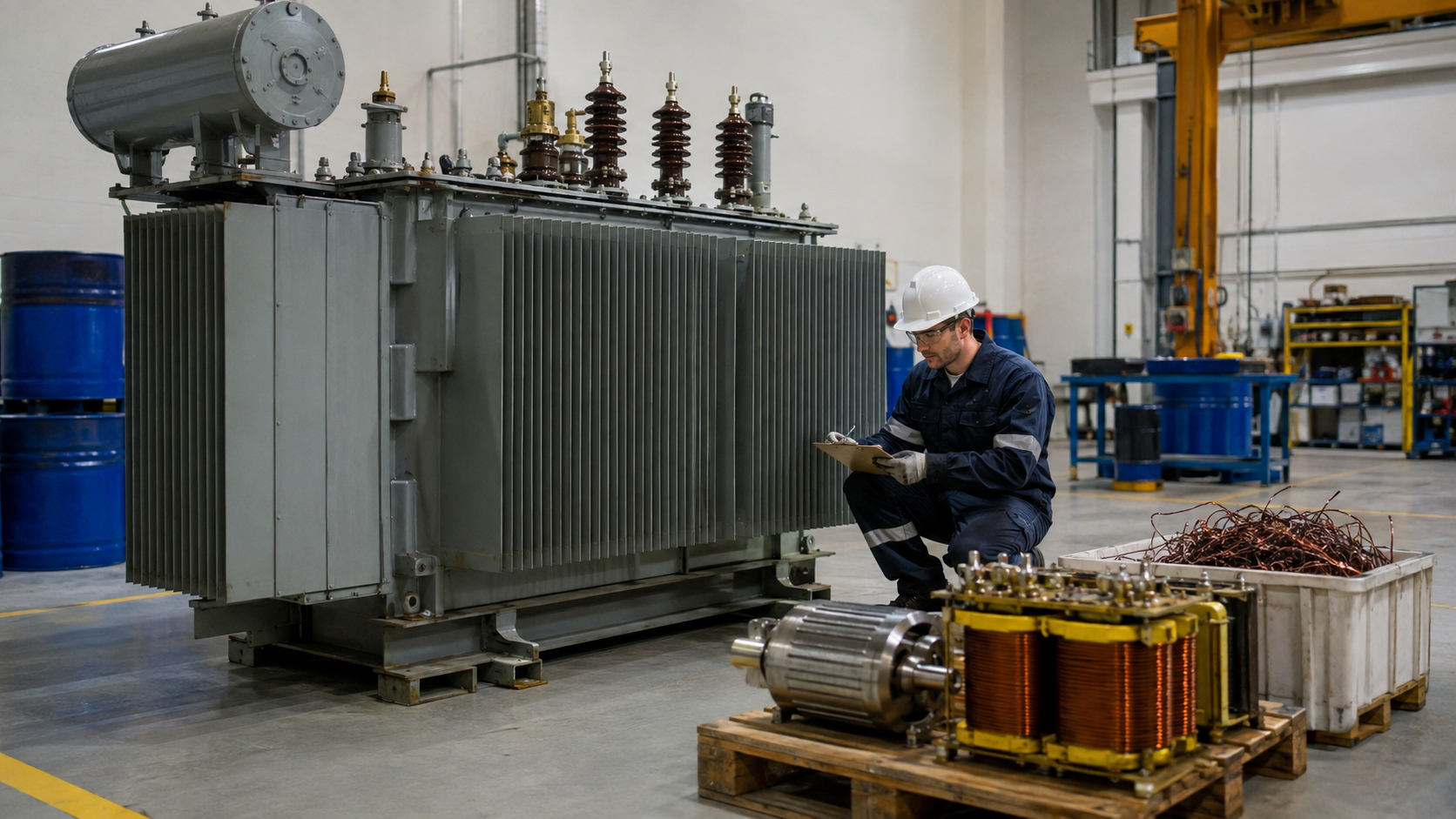
Transformer sizing is more than dividing total load by a percentage. A reliable selection converts real load into kVA, applies demand and diversity, checks motors and harmonics, accounts for environment and future growth, and then coordinates primary and secondary protection. This guide provides the core formulas, a practical sizing workflow and breaker/fuse considerations for single- and three-phase transformers.
Transformer Sizing Formulas
For a load expressed in real power:
Required kVA = Load kW ÷ power factor
For measured voltage and current:
- Single phase: kVA = V × A ÷ 1,000
- Three phase: kVA = √3 × V × A ÷ 1,000
For a 240 kW three-phase load at 0.8 power factor, apparent power is 300 kVA. That is a starting value, not the final transformer rating.
Build a Diversified Load Schedule
List each load’s kW or kVA, voltage, phase, power factor, efficiency, duty and starting method. Separate continuous, intermittent, standby, cyclic and future loads. Apply demand and diversity factors supported by operating data or project criteria. Do not apply one arbitrary factor to every load.
Evaluate normal and contingency states separately. A standby load may be off in normal operation but important during an outage. Two process lines may never run together, while ventilation and lighting may be continuous.
Three-Phase Transformer Sizing Example
Consider 180 kW of diversified process load at 0.85 power factor, 40 kW of continuous auxiliary load at 0.9 power factor and 50 kVA reserved for growth:
- Process: 180 ÷ 0.85 = 211.8 kVA
- Auxiliary: 40 ÷ 0.9 = 44.4 kVA
- Future allowance: 50 kVA
- Total: 306.2 kVA
The next standard size might be 315 or 400 kVA depending on regional ratings, ambient conditions, starting duty and reliability. The engineer should check voltage drop, losses and actual loading rather than automatically adding a large margin.

Transformer Sizing Table: Full-Load Current
| Three-phase kVA | 400 V current | 480 V current | 11 kV current |
|---|---|---|---|
| 100 | 144 A | 120 A | 5.25 A |
| 250 | 361 A | 301 A | 13.1 A |
| 500 | 722 A | 601 A | 26.2 A |
| 1,000 | 1,443 A | 1,203 A | 52.5 A |
| 2,000 | 2,887 A | 2,406 A | 105 A |
These are calculated full-load currents. They are not breaker or cable ratings and do not include code factors or derating.
Motor Starting and Voltage Drop
A motor may draw several times rated current during starting. The transformer must keep terminal voltage within acceptable limits while other loads remain stable. Check motor size, starting current, starting time, allowable voltage dip and source impedance. Soft starters or variable-frequency drives can reduce starting current but may introduce harmonics.
Harmonic Loads
Variable-speed drives, UPS systems, rectifiers and large LED loads draw nonsinusoidal current. Harmonics increase winding and stray losses and can heavily load a neutral. Use a harmonic study or load spectrum to determine whether derating, a K-factor-rated design, electrostatic shielding or other construction is needed.
Ambient, Altitude and Cooling
Transformer rating assumes specified ambient and altitude. High temperature and thin air reduce cooling and insulation performance. Indoor dry-type units require room ventilation; liquid-filled transformers need radiator airflow, oil containment and fire provisions. Enclosures can restrict cooling and must be included in the thermal design.
Transformer Breaker Sizing
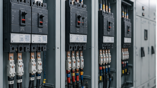
Calculate primary and secondary full-load current, then apply the governing electrical code and manufacturer recommendations. The device must carry permitted load, withstand magnetizing inrush and coordinate with transformer thermal and through-fault limits. Its interrupting rating must exceed prospective fault current.
Secondary breaker sizing also protects outgoing conductors and busbars. Large transformer impedance reduces secondary fault current; low impedance increases it. A short-circuit study is necessary before selecting the switchboard rating.
Transformer Fuse Sizing
Primary fuses can provide economical short-circuit protection, but fuse type and rating must tolerate energization inrush and coordinate with secondary protection. Verify voltage, continuous current, minimum and maximum clearing curves, interrupting rating and transformer damage curve. Do not use a generic fuse-size chart without the applicable code and actual fuse characteristic.
Oversizing and Undersizing
An undersized transformer overheats, has excessive voltage drop and ages rapidly. An oversized transformer costs more, may operate inefficiently at chronic light load, increases energization inrush and can raise available fault current. The goal is adequate capacity across realistic scenarios with a justified growth allowance.
Choose Construction and Package
After selecting kVA, define voltage, vector group, impedance, taps, cooling, temperature rise, efficiency, sound, enclosure and accessories. LBAJI’s 35 kV oil-immersed transformer supports project-specific ratings. Packaged systems can use a YBM-12 prefabricated substation or 35 kV new-energy box substation.
Verification and Testing
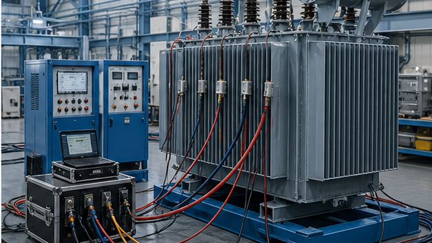
Review guaranteed losses, impedance, temperature rise and sound against the design. Factory tests commonly include winding resistance, ratio/vector group, impedance and load loss, no-load loss/current, insulation tests and functional accessory checks. Special tests should be specified before ordering.
Final Sizing Checklist
- Verify load schedule and operating scenarios.
- Convert kW to kVA with realistic power factors.
- Apply documented demand and diversity.
- Check motors, cyclic loads and harmonics.
- Apply ambient, altitude and enclosure corrections.
- Select a standard rating with justified growth.
- Check voltage drop, losses and fault current.
- Coordinate breakers or fuses with inrush and damage limits.
Step-by-step transformer sizing sequence
Calculate connected load, apply realistic demand and diversity, convert kW to kVA, add motor-starting and nonlinear-load effects, evaluate normal and contingency loading, then select the next suitable standard rating. Check voltage regulation and temperature after selecting kVA; do not assume a spare percentage solves every duty.
When the calculated size is not the final size
A larger transformer may be required by starting voltage dip, harmonics, cyclic loading, high ambient temperature or future growth. A smaller standard size may still work when loads are demonstrably noncoincident. Record the operating scenarios and assumptions so the decision can be reviewed later.
Technical references and further reading
The following independent sources support the standards, terminology, calculations, and safety context discussed in this guide:
- IEC 60076-1 power transformer standard — Scope, terminology, ratings, connection symbols, testing, safety, and general requirements for power transformers.
- U.S. Department of Energy: Distribution Transformers — Official definitions, efficiency requirements, test procedures, and regulatory resources for distribution transformers.
- OSHA electric power transmission and distribution requirements — Safety requirements relevant to construction and work around electric power transmission and distribution equipment.