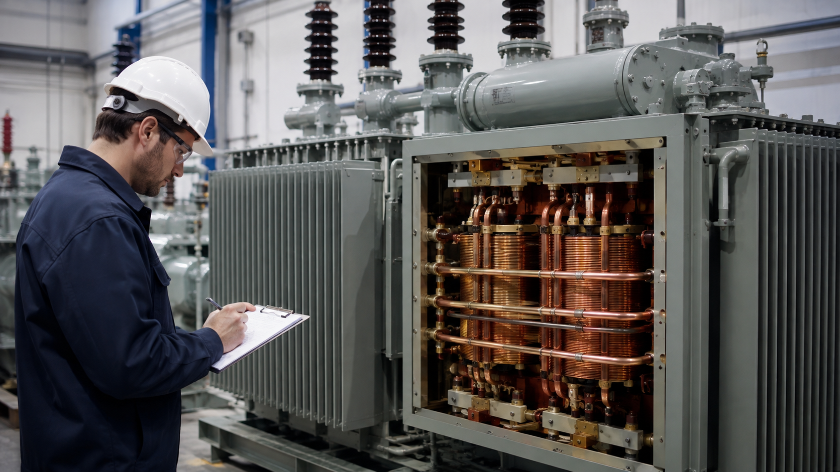
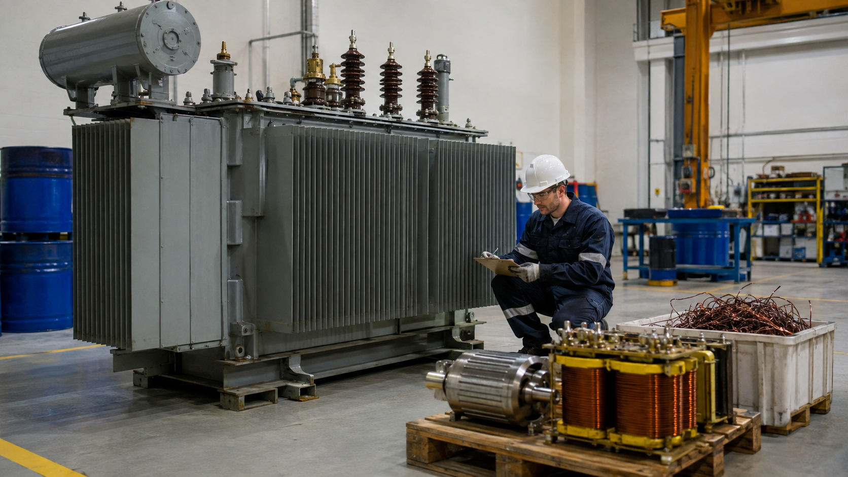
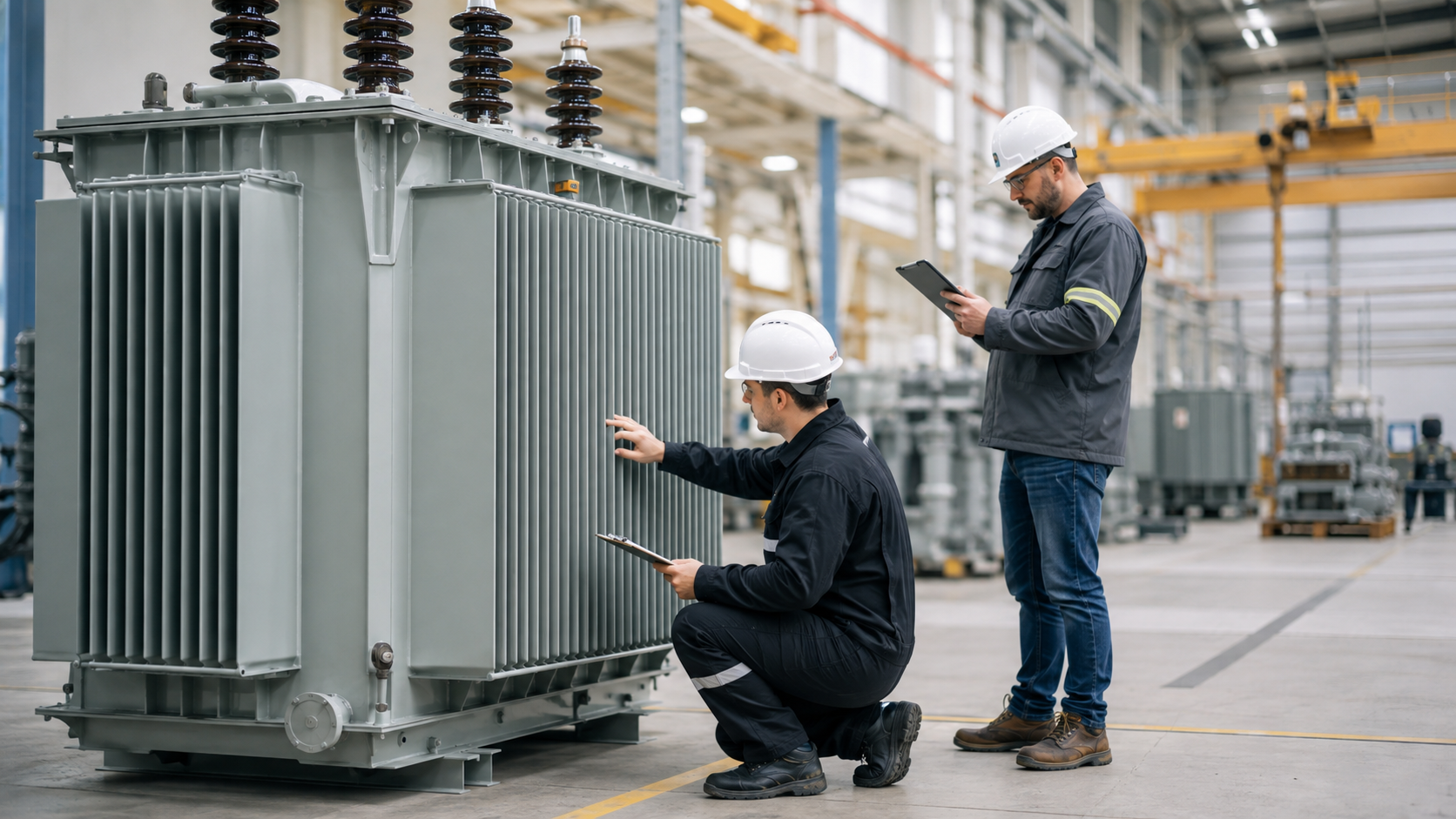
A step-up transformer raises alternating voltage from the primary side to the secondary side. For approximately the same apparent power, the higher-voltage side carries lower current. Step-up units connect generators and renewable plants to grids, adapt industrial equipment and reduce transmission losses. This guide covers voltage/current relationships, single- and three-phase sizing, 208-to-480 V applications, reverse use and DC limitations.
How a Step-Up Transformer Works
Alternating current creates changing magnetic flux in the core. Secondary voltage follows the turns ratio:
V₂/V₁ = N₂/N₁
If the secondary has more turns, its voltage is higher. Current ratio is inverse:
I₂/I₁ ≈ N₁/N₂
Actual output power is lower than input because winding and core losses produce heat.
Step-Up vs Step-Down
“Step-up” and “step-down” describe the direction of use. A 480/208 V transformer used from 480 to 208 V steps down. Some units may operate in reverse from 208 to 480 V, but only when the manufacturer confirms voltage, taps, inrush, grounding and insulation suitability.
Quick Comparison and Selection Table
Use this table as a quick review of the main engineering and procurement decisions explained in the article.
| Decision area | Practical meaning | What to verify |
|---|---|---|
| How a Step-Up Transformer Works | Alternating current creates changing magnetic flux in the core. | Secondary voltage follows the turns ratio: V₂/V₁ = N₂/N₁ If the secondary has more turns, its voltage is higher. |
| Step-Up vs Step-Down | “Step-up” and “step-down” describe the direction of use. | A 480/208 V transformer used from 480 to 208 V steps down. |
| Single-Phase Sizing | For single phase: kVA = volts × amps ÷ 1,000 A 20 kVA transformer stepping 120 V to 240 V carries about 166.7 A at 120 V and 83.3 A at 240 V at full load. | Protection and conductor sizing must follow the applicable code and inrush requirements. |
| Three-Phase Step-Up Transformer | For balanced three phase: kVA = √3 × line voltage × line current ÷ 1,000 A 150 kVA transformer at 208 V carries about 416 A on the low side and about 180 A at 480 V. | Connection and vector group determine neutral and phase shift. |
| 208 to 480 V Applications | A 208-to-480 V step-up transformer may supply machinery designed for 480 V from a 208 V facility. | Specify load kVA, duty, power factor, motor starting, phase, frequency, primary/secondary connection and grounding. |
Single-Phase Sizing
For single phase:
kVA = volts × amps ÷ 1,000
A 20 kVA transformer stepping 120 V to 240 V carries about 166.7 A at 120 V and 83.3 A at 240 V at full load. Protection and conductor sizing must follow the applicable code and inrush requirements.
Three-Phase Step-Up Transformer
For balanced three phase:
kVA = √3 × line voltage × line current ÷ 1,000
A 150 kVA transformer at 208 V carries about 416 A on the low side and about 180 A at 480 V. Connection and vector group determine neutral and phase shift.
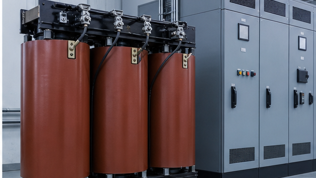
208 to 480 V Applications
A 208-to-480 V step-up transformer may supply machinery designed for 480 V from a 208 V facility. Specify load kVA, duty, power factor, motor starting, phase, frequency, primary/secondary connection and grounding. A delta or ungrounded output may not satisfy equipment needing a grounded neutral.
120/240 V Step-Up Applications
A small transformer can raise 120 V to 240 V, but the supply circuit must carry roughly twice the output current for the same kVA. Confirm whether the load needs a 240 V two-wire output, split-phase 120/240 V neutral or isolation. A simple buck-boost autotransformer arrangement may adjust voltage but does not provide galvanic isolation.
Generation Step-Up Transformers
Power plants and renewable systems generate at a lower voltage and step up for collection/transmission. Large generation step-up units are designed for high continuous loading, fault forces, harmonics, grid disturbances and terminal interfaces. Protection includes differential, restricted earth fault, overexcitation, temperature and mechanical devices.
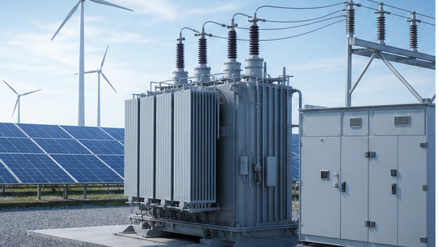
LBAJI’s 35 kV oil-immersed transformer can serve step-up duties when configured for the project. A 35 kV new-energy box substation integrates transformation and switching for solar or wind collection.
Can a Step-Down Transformer Be Used in Reverse?
Sometimes, but not automatically. Rated low-voltage winding input may produce lower-than-expected high-side output because original regulation was designed in the opposite direction. Taps may be inappropriate, inrush can differ, neutral/grounding may change and certifications may not cover reverse use. Obtain manufacturer approval.
DC Step-Up Is Not a Conventional Transformer
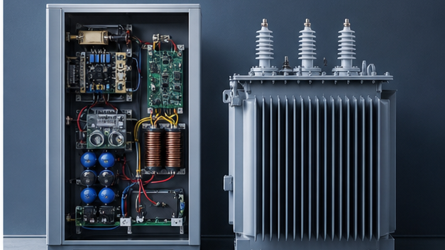
Steady DC does not create continuously changing core flux. Applying DC directly to a normal transformer can overheat and damage the winding. A DC-to-DC boost converter electronically switches current, stores/transfers energy through inductors or a high-frequency transformer, then rectifies/controls the output.
Protection and Inrush
Primary protection must carry normal current and tolerate magnetizing inrush while clearing faults. Secondary protection protects outgoing conductors and loads. Breaker/fuse curves should coordinate with the transformer damage curve and upstream/downstream devices. Available fault current depends on source and transformer impedance.
Selection Checklist
- Input/output voltage, phase and frequency.
- Diversified load kVA and power factor.
- Motor starting or cyclic duty.
- Winding connection, neutral and vector group.
- Impedance, taps and regulation.
- Dry/oil construction, enclosure and environment.
- Primary/secondary protection and fault level.
- Efficiency, sound, temperature and tests.
Common step-up transformer applications
Step-up units connect generators and renewable plants to higher-voltage networks, supply 480 V equipment from a 208/240 V source, and reduce current for power transfer. The transformer must match frequency, phase, grounding and load type; an electronic DC boost converter is a different device.
Custom step-up specification checklist
Provide input/output voltage, kVA, phase, frequency, vector connection, neutral, taps, impedance, duty cycle, inrush-sensitive protection, enclosure, temperature and terminal arrangement. If the unit is back-fed, verify manufacturer approval and protection requirements because available taps and inrush behavior may differ from the original direction.
Technical references and further reading
The following independent sources support the standards, terminology, calculations, and safety context discussed in this guide:
- IEC 60076-1 power transformer standard — Scope, terminology, ratings, connection symbols, testing, safety, and general requirements for power transformers.
- U.S. Department of Energy: Distribution Transformers — Official definitions, efficiency requirements, test procedures, and regulatory resources for distribution transformers.
- OSHA electric power transmission and distribution requirements — Safety requirements relevant to construction and work around electric power transmission and distribution equipment.