A switchgear maintenance checklist should document the equipment being serviced, the authorized work scope, energy isolation, condition findings, tests, corrective actions and the final return-to-service decision. It is not a universal list of tasks to perform inside an energized cabinet. The inspection level and interval depend on the switchgear model, voltage, duty, environment, previous faults and the site’s electrical-safety program. Use the checklist below to plan and record qualified work, then apply the exact manufacturer manual and approved procedure for test methods, limits and switching steps.
Start with the asset and the reason for maintenance
Record the site, room, lineup, cubicle, serial number, operating voltage, feeder name and current one-line drawing revision. Note whether the visit is routine, condition-triggered, post-fault or a return after repair. These identifiers prevent test results from being attached to the wrong breaker or bus section. Capture the previous inspection record, trip history, load trend and known defects before deciding the work scope. An inspection finding that was deferred last year should appear explicitly in today’s plan, not disappear into a generic “visual check” box.
Define what will remain energized elsewhere in the lineup, how the work boundary will be established, and who is responsible for switching, testing and approval. A visual walk-through from outside a closed enclosure differs from opening compartments, racking a breaker or testing a relay. The risk controls, qualifications and permits must match the actual activity. OSHA 29 CFR 1910.333 addresses electrical safety-related work practices in the United States; other jurisdictions and project rules may impose additional requirements.
A usable stage-by-stage checklist
The following table is a planning and record structure. It deliberately does not prescribe a universal torque value, insulation-resistance threshold or maintenance interval. Those values belong to the exact equipment instructions and the approved test plan. Add a measured value and acceptance criterion to the job sheet whenever a test is actually required.
| Bühne | Record before sign-off | Stop or escalate when |
|---|---|---|
| Scope and identification | Asset ID, drawing revision, work order, responsible persons, previous defects | Cabinet identity or circuit boundary cannot be confirmed |
| Safe work setup | Approved isolation, lockout/tagout, test for absence of voltage, earthing and work boundary as applicable | Any source, backfeed or stored energy is unresolved |
| External condition | Doors, seals, corrosion, contamination, moisture, ventilation, indications and alarms | Damage or abnormal indication suggests an unsafe condition |
| Internal/mechanical work | Only authorized tasks, interlocks, operating mechanism, contacts or racking system per model manual | Unapproved parts, binding, abnormal wear or missing interlock evidence |
| Electrical/protection tests | Method, instrument ID, conditions, measured result, limits and relay settings | Result is outside approved limits or cannot be interpreted |
| Return to service | As-left configuration, removed tools, covers, settings, independent checks and approval | Any temporary jumper, open work item or test configuration remains |
This is a qualitative checklist, not a substitute for model-specific test criteria. The NFPA publication catalog for NFPA 70B identifies the electrical equipment maintenance standard; use the contractually applicable edition and the full standard text rather than inferring requirements from a summary.
Visual condition before opening a cabinet
From a safe position, look for enclosure deformation, water entry, dust accumulation, heat discoloration, damaged seals, blocked ventilation, unusual sound or smell, and alarms. Check that labels and mimic diagrams still correspond to the as-built circuit. Compare the present indications with the control-room record when remote monitoring exists. A clean front panel alone does not show the state of internal contacts or insulation, but obvious external damage can justify stopping before further work.
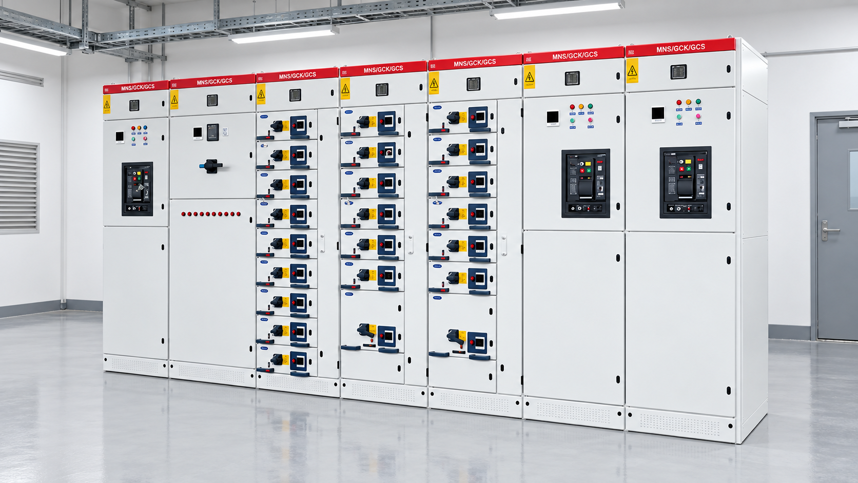
Different products need different checks. A KYN28A-12 typgeprüfte, ausfahrbare Schaltanlage may have racking and compartment features that a fixed RMU does not. A GGD low-voltage lineup has another internal arrangement and protection set. The photograph illustrates the product family; it cannot establish that a particular compartment is de-energized. Identify the actual panel and manual before opening any door.

Isolation, lockout and verification
The maintenance plan must identify every possible source: normal supply, alternate feeder, generator, photovoltaic or battery backfeed, control power and stored energy. Qualified personnel apply the site’s approved isolation and lockout/tagout process. Absence of voltage is verified with an appropriate method and instrument at the relevant points before work starts; a front-panel indicator alone is not a universal proof of safe isolation. Protective grounding or earthing is applied where required by the work method and equipment design. Never assume that an open breaker has isolated all conductors.
Document the isolation points, who applied controls, when they were verified, and any adjacent energized equipment. The procedure should also describe how the state changes when a test temporarily requires power. This is a controlled exception within the work plan, not an informal step. If the team cannot explain how a cable or bus section is separated from every source, stop and resolve the diagram before opening equipment. The OSHA guidance above is one relevant U.S. reference; the equipment manual and local legal requirements determine the complete procedure.
Mechanical inspection and cleaning
Once the approved safe condition is established, check only the parts covered by the work scope. Examples include enclosure hardware, accessible insulation surfaces, cable terminations, bus connections, interlocks, breaker mechanism, racking tracks and shutters. Record the as-found condition before cleaning or adjusting. Use only approved materials and methods; an arbitrary solvent, lubricant or compressed-air blast can harm insulation, seals or mechanisms. Torque fasteners only to the applicable manufacturer value using the specified method. “Tightened all connections” without locations, values or condition evidence is not a useful record.
Check signs of tracking, carbon deposits, corrosion, water paths and overheating. When a component shows damage, investigate the cause as well as the symptom. Replacing a discolored connector without assessing load, contact pressure or environmental ingress may leave the failure mechanism in place. For withdrawable gear, evaluate the exact breaker and cubicle interface under its manufacturer’s procedure; do not generalize from another model. If a repair changes the configuration, update drawings and spare-parts records.

Electrical tests and protection checks
Choose tests to answer a question. Insulation-resistance measurements can reveal gross insulation problems, but interpretation depends on test voltage, temperature, humidity, connected electronics and historical results. Contact-resistance measurements, mechanical timing, primary or secondary injection, relay functional tests, CT checks and control-circuit checks may be relevant to particular devices. None should be ordered simply because it appears on a generic internet checklist. The approved test plan should state setup, isolation, instrument, units, expected limits and who will interpret deviations.
Protection settings need special control. Save an as-found setting file before changes, compare against the approved coordination study, record every adjustment and save the as-left file. A relay can test correctly yet still be set incorrectly for the network. Similarly, a breaker can operate mechanically but fail to coordinate with upstream or downstream devices. The IEC 62271-200 scope for AC metal-enclosed switchgear is relevant to the assembly, but it does not provide a universal field-test recipe for every installed component.
Document defects in a way that drives action
For each finding, record location, severity, evidence, immediate control, recommended repair, owner and due date. Distinguish a defect that prevents energization from one that can be monitored under a documented risk decision. Attach photos only when safe and permitted. Trends are often more informative than a single value: compare measured results with previous tests taken under comparable conditions, and explain any method change. Keep instrument calibration and test conditions with the result so the next team knows whether a change is real.
Before return to service, confirm that temporary leads and jumpers are removed, covers are installed, interlocks and indications match the approved condition, settings are correct, and the work boundary can be released. An independent check may be appropriate for critical feeders. The operating authority should approve the final switching state and record the actual restoration time. Maintenance is not complete when tools are packed; it is complete when the equipment is safe, functional and traceable.
How often should switchgear be maintained?
Do not copy a fixed interval from an unrelated facility. Start with the manufacturer manual and the applicable maintenance program, then adjust for operating cycles, fault interruptions, contamination, humidity, thermal loading and condition-monitoring evidence. A quiet indoor lineup and an outdoor coastal installation do not age in the same way. More frequent checks may be justified after flooding, a fault or an abnormal alarm. Conversely, opening a sealed unit unnecessarily can introduce risk. Separate non-intrusive observations from outage-based tests so the plan does not create needless interruptions.
For surrounding context, read our switchgear fundamentals guide, air-insulated medium-voltage switchgear guide und Niederspannungs-Schaltanlagen-Leitfaden. These explain different assemblies; none replaces the exact installed-equipment manual. A model-specific operation and maintenance manual illustrates why a generic checklist must be adapted.
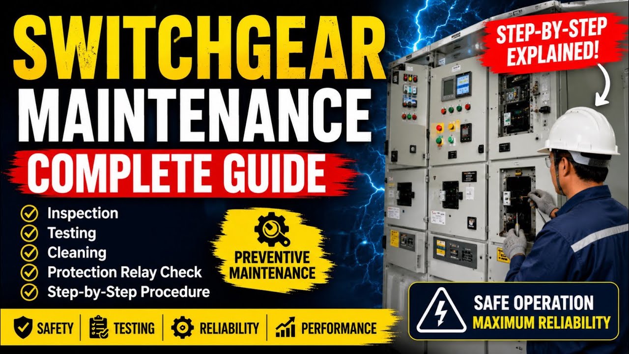
Further viewing: Maintenance Knowledge Hub’s educational video introduces visual inspection and maintenance stages. It does not authorize work on any specific live assembly.