A circuit breaker for motor protection must handle normal running current, starting current and fault current without nuisance tripping or leaving the motor and conductors unprotected. A motor branch circuit normally combines short-circuit protection, overload protection, a switching device and a motor starter or drive. The breaker is only one part of the protection system. Select it from the motor nameplate, starting method, conductor data, available fault current and the coordination requirements of the installation.
Separate overload and short-circuit duties
Motor overload protection responds to sustained heating caused by excessive load, loss of cooling or a phase problem. Short-circuit protection clears a much larger fault current quickly. A molded-case breaker may provide instantaneous or adjustable short-circuit protection while a separate overload relay protects the motor during acceleration and running. A breaker with the correct ampere rating is not automatically a complete motor-protection solution.
Start with the motor full-load current from the nameplate and the governing electrical code. Do not replace the nameplate value with a casual clamp-meter reading. The nameplate reflects the motor’s rated operating point, while measured current may be affected by load, voltage imbalance and temporary conditions. Record voltage, phase, frequency, service factor, locked-rotor current where available and the starter or drive type.
| Selection input | Pourquoi c'est important | Éléments de preuve à vérifier |
|---|---|---|
| Full-load current | Sets the design basis for conductors and protective devices | Motor nameplate and code table |
| Starting current | Determines whether instantaneous protection will tolerate acceleration | Locked-rotor data, starter curve or drive settings |
| Available fault current | Determines the required interrupting and short-circuit rating | Utility or fault-study calculation |
| Motor starter | Defines overload, contactor and coordination behavior | Starter data sheet and coordination table |
| Environnement | Affects enclosure, temperature and cooling | Panel schedule, ambient and installation drawing |
Allow for starting current
A direct-on-line motor can draw several times its running current during acceleration. If the breaker trips immediately at every start, its instantaneous setting may be too low for the actual motor, or the motor may be mechanically overloaded. Increasing the breaker without checking the conductors and starter is unsafe. Review the time-current curve and confirm that the overload relay, breaker and contactor are coordinated for the expected acceleration time.
Star-delta starters, soft starters and variable-frequency drives change the current profile. A drive may limit acceleration current but introduce harmonics, leakage current or a special short-circuit rating requirement. A soft starter may still draw a large current during bypass or a difficult start. Use the equipment manufacturer’s recommended protection type and verify whether the breaker is approved upstream of the device.
Choose the breaker family
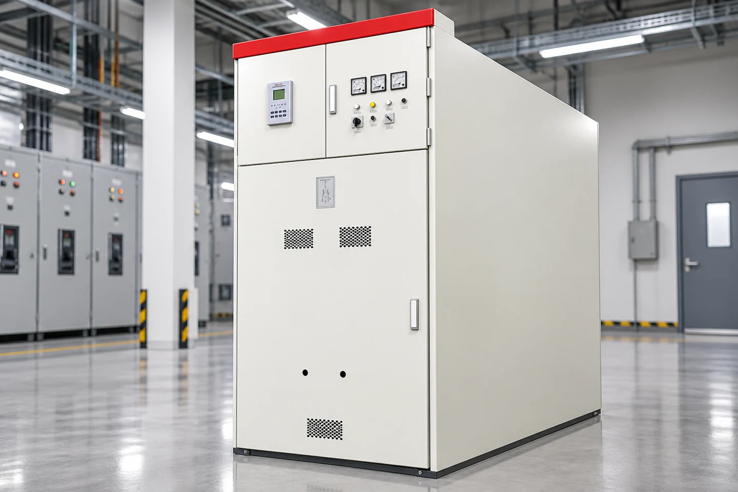
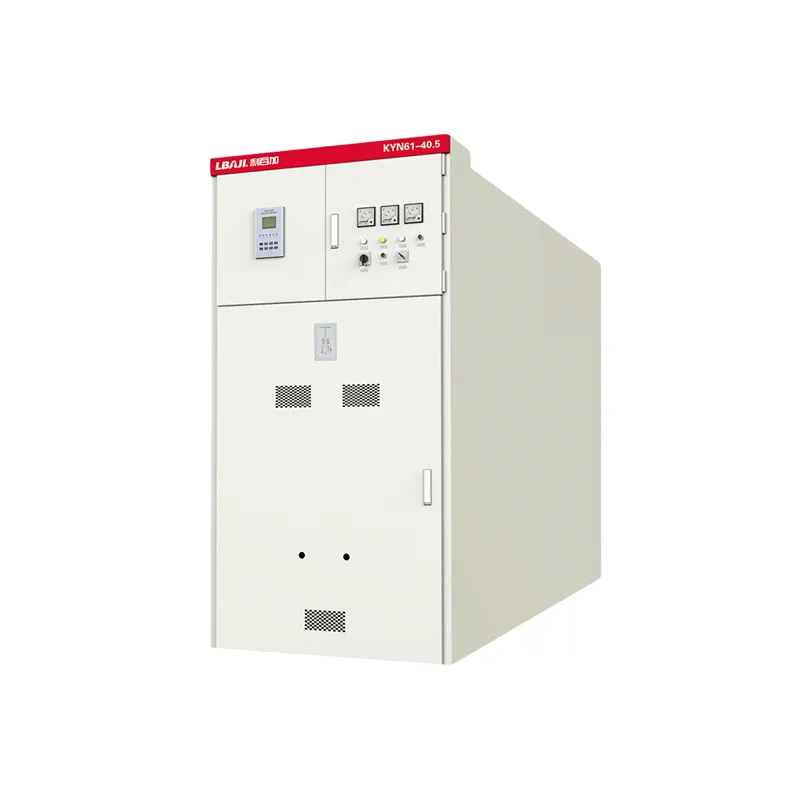
Small branch motors may use a miniature or motor-protection circuit breaker in a tested assembly. Larger feeders often use an MCCB or ACB with adjustable protection. A withdrawable low-voltage lineup can add isolation, shutters and a defined maintenance position. The exact family must match the panel bus system, terminal arrangement, interrupting capacity and enclosure rating. Product photos show the enclosure form, not the installed trip unit or motor curve.
Check interrupting and withstand ratings
The breaker interrupting rating must be at least the prospective short-circuit current at its installation point. Consider transformer impedance, utility contribution, generators, motors and alternate sources. The assembly short-circuit rating may be limited by the busbar, starter, contactor or feeder components even when the breaker itself has a higher rating. Confirm the complete combination with a tested or engineered coordination method.
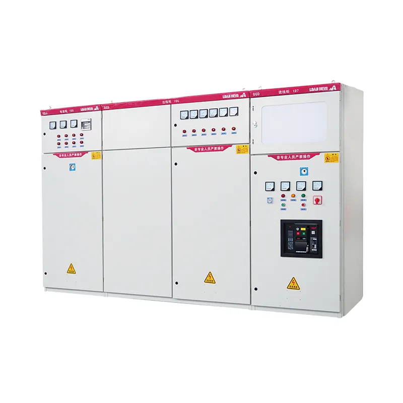
For industrial panels, review short-circuit current rating, short-time withstand, peak withstand and any series-rating restrictions. Do not assume that a breaker approved in one enclosure is automatically suitable in another. Temperature rise, ventilation, conductor length and terminal hardware can change the result. The LBAJI Tableau basse tension GGD page is a product reference; the project schedule must control the exact breaker and feeder data.
Coordinate overload protection
Set the overload relay from the motor and starter instructions, not from the breaker handle position. The overload should protect the motor while allowing normal acceleration. Verify phase-loss and phase-imbalance behavior where required. A motor can overheat without exceeding the breaker instantaneous threshold, especially when a bearing, pump or fan is mechanically restricted.
Electronic trip units may provide long-time, short-time and instantaneous functions. Their settings need a coordination study so the motor feeder clears before an upstream main breaker when possible. Keep the trip curve, setting record and test results with the panel documentation. Changes to motor size, starter type or transformer capacity require a new review.
Application in switchgear and control panels
Motor feeders often share a lineup with lighting, process heaters and variable-speed drives. Separate power and control wiring, provide clear labels and maintain the required creepage and clearance. A withdrawable feeder should have a defined connected, test and isolated position. Interlocks should prevent unsafe movement or closing. The MNS/GCK/GCS withdrawable switchgear family illustrates why feeder position and mechanical interlocks are part of the protection design.
Consider the motor environment
High ambient temperature, altitude, dust, moisture and frequent starts can reduce the available rating. Enclosure ventilation may change the thermal conditions around the breaker and overload relay. A motor in a washdown area may need a different enclosure and cable-entry method than a dry indoor motor. Review condensation, corrosion, ingress protection and the maintenance access required by the plant.
For outdoor or renewable-energy equipment, control-source behavior and remote trips may matter as much as current. A photovoltaic cabinet can feed motors through an inverter or auxiliary distribution system, so backfeed and stored energy must be documented. The Armoire BWG-800 is an example of a grid-connected product reference, not a generic motor-feeder specification.
Test et mise en service
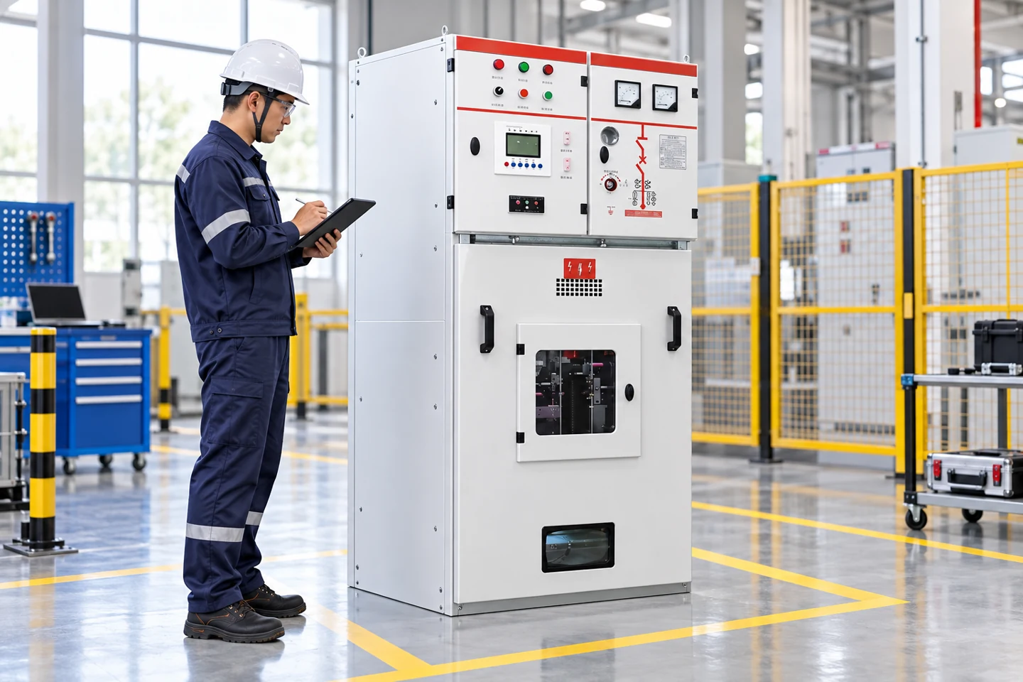
Before energizing, verify breaker identity, trip-unit settings, conductor terminations, phase sequence, motor rotation, overload class, contactor coil voltage and protective-earth continuity. Test the breaker mechanically and electrically using the manufacturer’s method. Confirm that the motor starts without excessive current or vibration and that the overload and emergency-stop circuits operate as designed.
Record measured current on all phases, acceleration time, voltage balance, trip settings and any thermal observations. Do not use a successful first start as proof of coordination. A motor may start unloaded and later trip when the pump, compressor or conveyor reaches process load. Retest under the real operating condition and after any process change.
Maintenance checklist
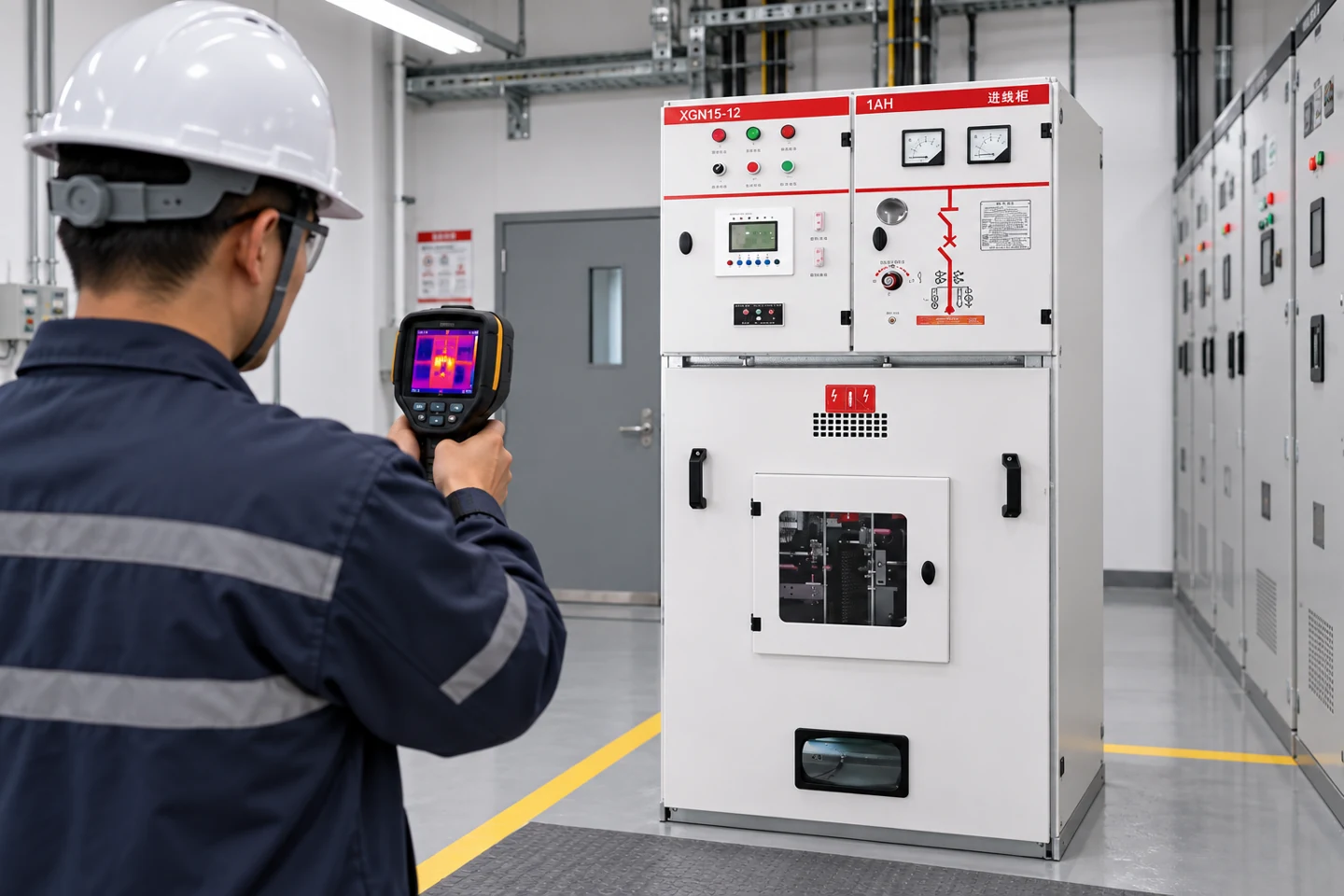
Maintenance should include visual inspection, cleaning, torque verification, thermal scanning, breaker mechanism checks, overload testing and review of nuisance trips. Look for discolored terminals, loose control wires, blocked ventilation and signs of water or dust. Compare phase currents and investigate imbalance rather than simply increasing the trip setting. Keep spare trip units, contactors and overload elements identified by exact part number.
When a breaker is replaced, verify the frame, trip plug, accessory contacts, bus connection and short-circuit rating. Recheck the coordination record and update the panel drawing. The Guide de test des équipements de commande explains why visual, insulation, contact and functional tests answer different questions.
Final selection sequence
Define the motor and starting method, calculate the available fault current, select the conductor and starter, choose a breaker with the required interrupting rating, coordinate the overload and verify the enclosure. Then review the complete assembly with the single-line diagram, motor schedule and protection study. This sequence prevents the common mistake of choosing a breaker by running amperage alone.
For a safe specification, ask the supplier to state breaker frame and trip type, continuous current, interrupting rating, overload device, coordination category, control accessories, enclosure rating, ambient derating and test standard. Ask which values are guaranteed and which depend on options. That documentation is more useful than a generic “motor breaker” label.
Motor protection also has to account for restart behavior. A process may permit an automatic restart after a short voltage sag, or it may require a manual reset after an overload. Document the restart philosophy, emergency-stop response and any permissive from the process controller. A breaker that remains closed while a starter drops out can produce a different hazard from a breaker that trips and requires inspection.
For reversing starters and multi-speed motors, check every contactor path and overload element. Interlocking prevents two incompatible contactors from closing together, while the protective device must clear a fault on either path. For a drive-fed motor, check the drive’s DC bus discharge time and the upstream disconnect. The motor schedule should identify all energy sources, not only the normal incomer.
When a motor is supplied from a transformer, review inrush on both sides and the effect of transformer impedance on available fault current. A long feeder can reduce fault current but increase starting voltage drop. Verify that the motor still reaches speed within the overload class and that the breaker clears a remote fault within the permitted time. Keep these calculations with the protection study.