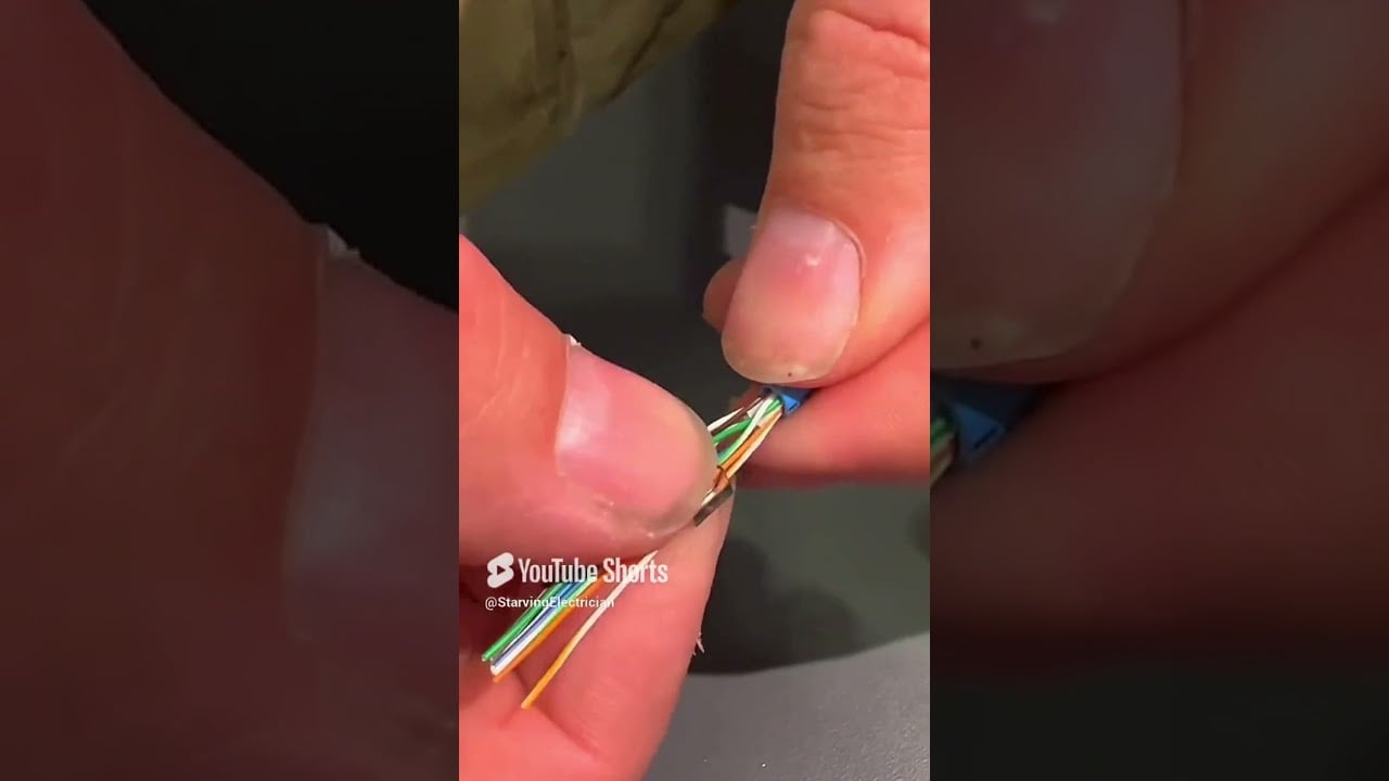
Low-voltage wiring is wiring that operates below the voltage boundary defined by the applicable code, standard or project specification. The phrase is not universal: a building-power circuit, a 24 V control circuit, a fire-alarm loop and an Ethernet cable may all be called low voltage in different contexts, yet they have different insulation, separation, installation and testing requirements. Identify the system and governing rule before selecting a cable or assuming it is safe to touch.
Power, control and signal are different categories
Low-voltage power wiring can supply lighting, receptacles or equipment. Control wiring may operate a contactor, valve or relay at a lower control voltage. Extra-low-voltage signal wiring may carry sensors, access control, data or communications. The voltage alone does not define the required installation method. Energy, short-circuit behavior, fire function, insulation, polarity, electromagnetic compatibility and separation from higher-energy circuits also matter.
Use the project code and equipment documentation for the boundary. The OSHA electrical-installation requirements address guarding, identification and safe use of electrical equipment in the workplace. A 24 V circuit can still start a fire, damage electronics or carry stored energy. “Low voltage” is not permission to bypass isolation, overcurrent protection or qualified-work rules.
| Wiring role | Typical purpose | Design checks |
|---|---|---|
| Low-voltage power | Lighting, receptacles, small equipment or a panel feeder | Conductor ampacity, voltage drop, overcurrent protection, grounding and enclosure |
| Control | Coils, interlocks, PLC I/O and motor-control commands | Control voltage, fail state, fuse, terminal numbering and isolation from power |
| Instrumentation | Temperature, pressure, flow and analog measurement | Signal range, shield, reference, noise and calibration |
| Safety circuit | Emergency stop, guard switch or safety relay input | Required safety function, diagnostics, reset and fault response |
| Data and communication | Ethernet, RS-485, fieldbus or access-control data | Impedance, topology, cable category, shielding and separation |
Select conductors from the real installation
Start with load current, conductor material, insulation temperature, installation method, ambient temperature, grouping and permitted voltage drop. A cable in free air has different heat dissipation from one in a crowded trunking system. Long control runs may need a larger conductor to preserve relay or solenoid voltage. Instrument and data cables are selected for signal integrity rather than only ampacity. Confirm conductor size, insulation rating, flame or smoke performance and approvals with the governing code and equipment manufacturer.
Protect every circuit with a device suited to the conductor and load. A low-voltage control fuse may protect a transformer secondary, while a PLC output needs protection compatible with its electronic switching. Do not put a sensitive analog loop behind a device that introduces unacceptable leakage or common impedance. Identify polarity and return conductors. For DC systems, reverse polarity can damage devices even if the nominal voltage is low.
Keep circuits separated and identifiable
Separate power conductors from sensitive signals and communications according to the applicable code and equipment instructions. Use partitions, separate trunking or spacing when needed. Cross different systems at an appropriate angle where practical, avoid long parallel runs and terminate shields according to the signal and EMC design. A tidy bundle is not automatically a good electrical design if it places a fast-switching drive cable beside a thermocouple or communication pair.
Use terminal blocks and wire numbers that match the schematic. Label both ends of field cables and identify spare conductors. Keep safety circuits visibly distinct from ordinary control circuits. Bond or isolate shields as specified; inconsistent shield termination can create noise loops or defeat the intended reference. Keep enclosure doors, gland plates and cable entries bonded where the design requires a protective-earth path.
Control wiring inside a panel
A panel control circuit should show its source, isolation, fuse or breaker, control device, load and return. For a contactor coil, document the stop chain, permissives, overload contact, start command and auxiliary feedback. For a PLC, identify each input and output type, common reference and field device. For a safety relay, show reset, feedback monitoring and the safe state. These details prevent a common mistake: connecting a device with the right voltage but the wrong output type or reference.
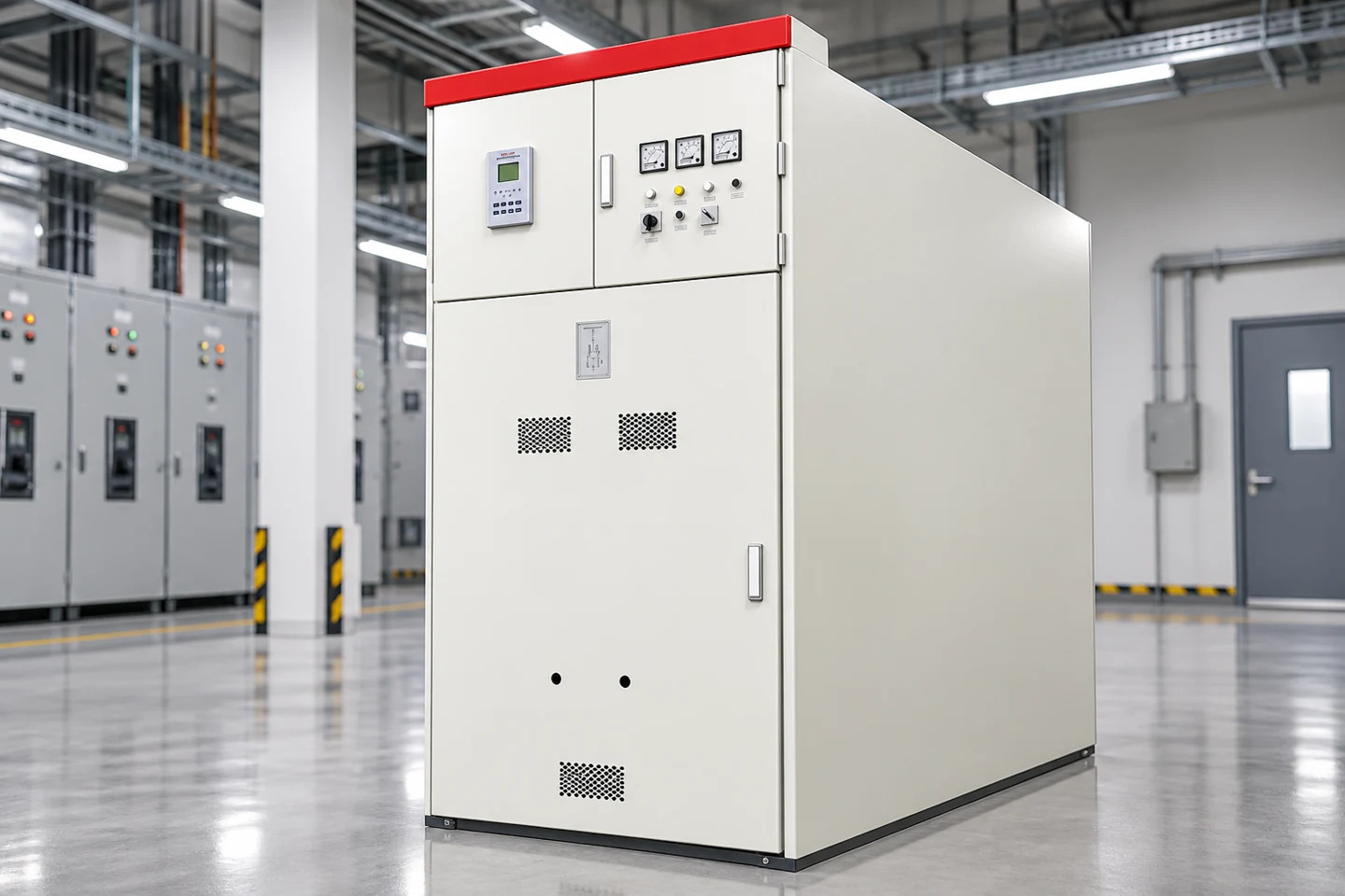
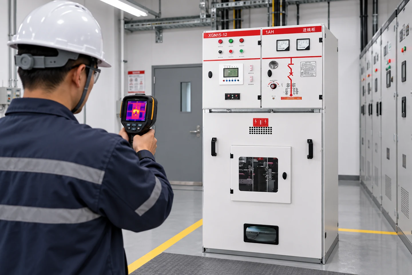
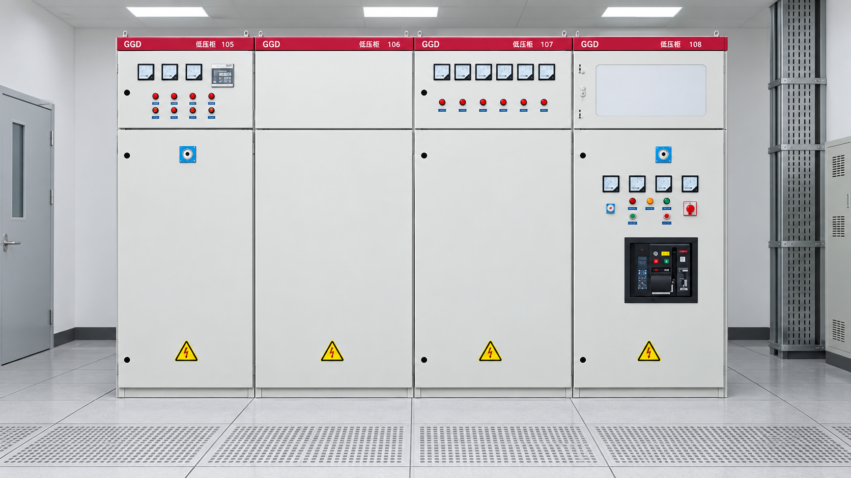
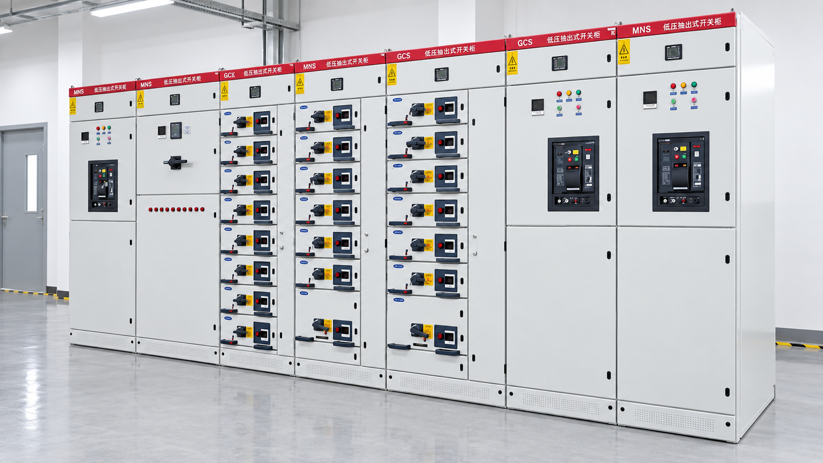
Le LBAJI GGD low-voltage switchgear illustrates a distribution enclosure with controls and protective devices. For withdrawable sections, the LBAJI MNS/GCK/GCS lineup shows why circuit identification and plug-in interfaces need a controlled schedule. The external cabinet image cannot determine the actual control voltage, terminal arrangement or installed protection of a purchased configuration.
PV and auxiliary low-voltage circuits
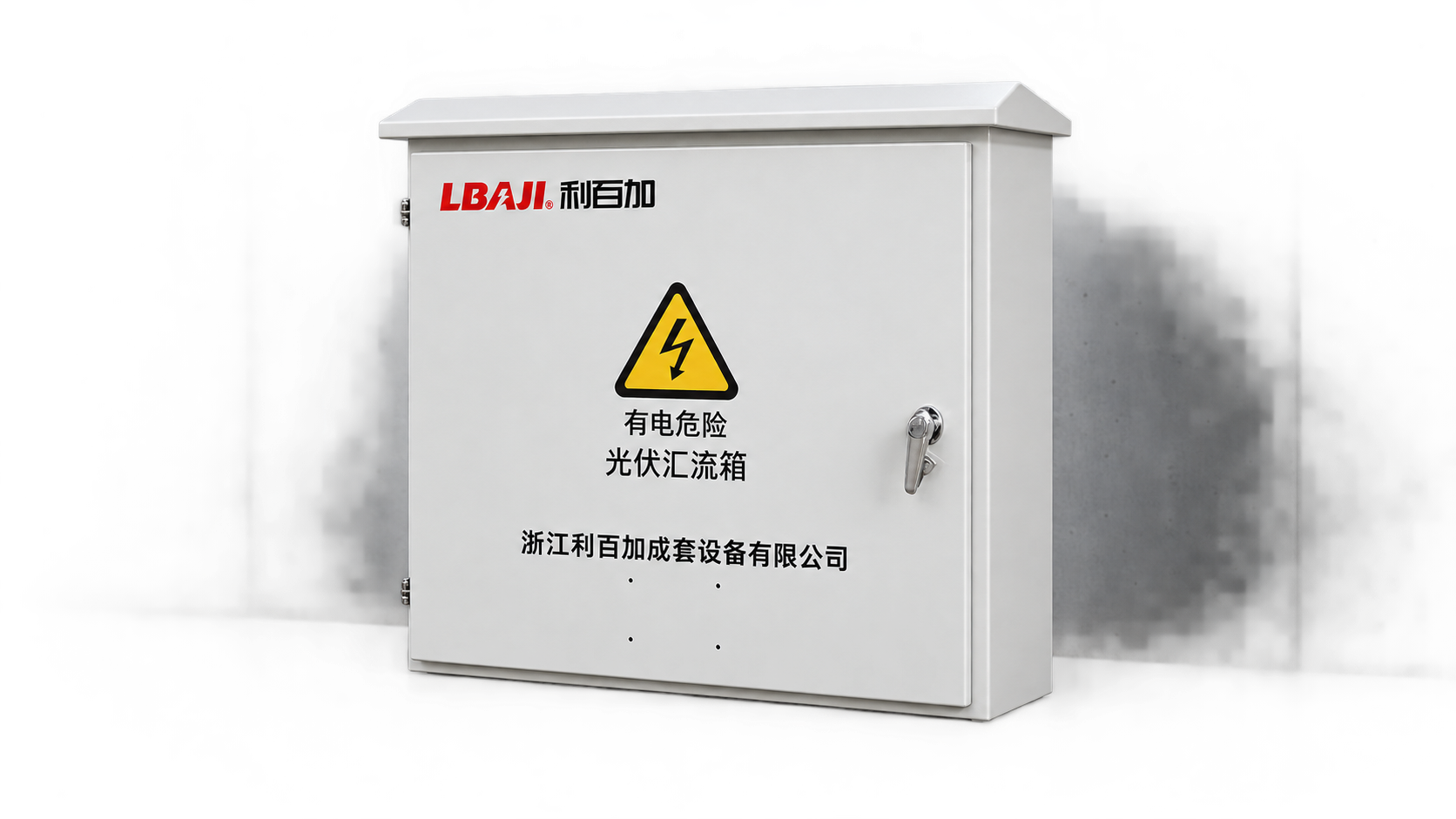
Photovoltaic equipment adds DC and AC boundaries, monitoring, communications and sometimes rapid-shutdown or protection functions. A PV cabinet may connect measurement, protection and grid-interface circuits, but each conductor must be identified by its source and isolation point. DC polarity, arc behavior and the absence of a natural current zero make PV wiring a specialized design. Do not call a DC combiner or grid-connected cabinet “ordinary low voltage” and omit the manufacturer’s wiring limits.
Le LBAJI BWG-800 photovoltaic grid-connected cabinet is a product reference for this type of application. Confirm the ordered voltage, current, protection, meter and communication arrangement from the product documentation. Its image is not a wiring diagram. Incoming and outgoing cables, protective earth, monitoring conductors and control power need separate identification in the project drawings.
Test et mise en service
Before energization, compare the installed wiring with the latest schematic and terminal schedule. Check conductor identification, polarity, continuity, protective-earth continuity, insulation where appropriate, fuse ratings and device settings. Do not megger a circuit with connected electronics unless the manufacturer permits it. Test analog values with a calibrated source and verify scaling in the controller. Test digital inputs and outputs at the field device, not only by forcing a PLC bit.
Functional commissioning should include normal operation, loss of supply, open-circuit and short-circuit responses where the approved procedure permits, emergency functions, interlocks, alarm reset and communication loss. Record as-found and as-left conditions. For network cabling, test the cable type and link performance using the method specified for that system. For fire or safety circuits, follow the dedicated standard and authority requirements.
Use lockout/tagout and an approved electrical safe-work method for tests that expose hazardous energy. The Guide de test des équipements de commande explains why continuity, insulation and functional tests answer different questions. A circuit can pass one and fail another.
Common low-voltage wiring mistakes
Typical failures include using a wire size without checking grouping, routing signal cable beside a drive output, leaving a DC return unidentified, mixing safety and ordinary commons, omitting a surge or flyback path, and changing a terminal without updating the drawing. Another error is assuming that a cable rated for the nominal voltage is suitable for the environment, flexing, fire performance or data frequency. Correct the design from the complete installation context.
Keep a controlled record of cable type, route, termination, test result and drawing revision. Photograph concealed routes before closing trays or walls. When a field change is required, obtain approval and update the as-built package. The value of low-voltage wiring is its predictable interface; undocumented changes remove that advantage.
Pay particular attention to transitions between systems. A sensor may leave a field junction box on shielded cable, enter a panel terminal strip, pass through an isolator and then appear at a PLC input. Each transition should have an identified reference and a stated common or shield treatment. A data cable may pass through a fire-rated wall or a tray with power conductors; the penetration, support and separation detail should be shown in the installation record. These small details make troubleshooting possible and help future technicians distinguish an intentional interface from an improvised splice.
Further viewing: The Electrical Engineering Portal’s educational material on low-voltage distribution helps explain circuit roles; follow local regulations and the installed equipment documentation for actual work.