Data center switchgear distributes power while supporting the operating states needed to keep critical loads supplied and maintain equipment. Its specification must connect source arrangements, fault duties, protection, controls and maintenance access to the facility’s resilience objectives. A lineup with two incomers does not by itself prove redundant operation or uninterrupted service. This guide explains how owners and buyers can review the electrical arrangement, dependencies and acceptance evidence before procurement. It does not assign a facility tier or claim that a catalogue product provides a particular uptime result; those conclusions need a defined architecture and appropriate project verification.
Define the facility’s required operating states
Start with the owner’s requirements for availability, maintenance and recovery. Identify which loads must remain supplied, which can transfer with an interruption and which can be shed. Separate IT loads from cooling, controls, security and other supporting systems. A resilient electrical design needs to consider the supporting services that keep the IT equipment usable, not just the rack power path.
Describe normal operation, planned maintenance and credible failures. Review a source outage, an unavailable bus section, a breaker under maintenance and a failed control supply. The owner and designer should agree what continues operating and what intervention is required in each state. Avoid equating a component count with a resilience result. The useful deliverable is a clear operating-state matrix linked to the electrical design and commissioning plan.
Trace the complete power path to the critical load
Map utility sources, transformers, generators, main distribution, UPS interfaces and downstream distribution. Identify the boundaries between switchgear and other equipment. The same upstream assembly may support several downstream paths, so check whether an apparent A/B arrangement shares a common source or bus. Redundancy needs to be assessed along the complete path rather than at one convenient drawing boundary.
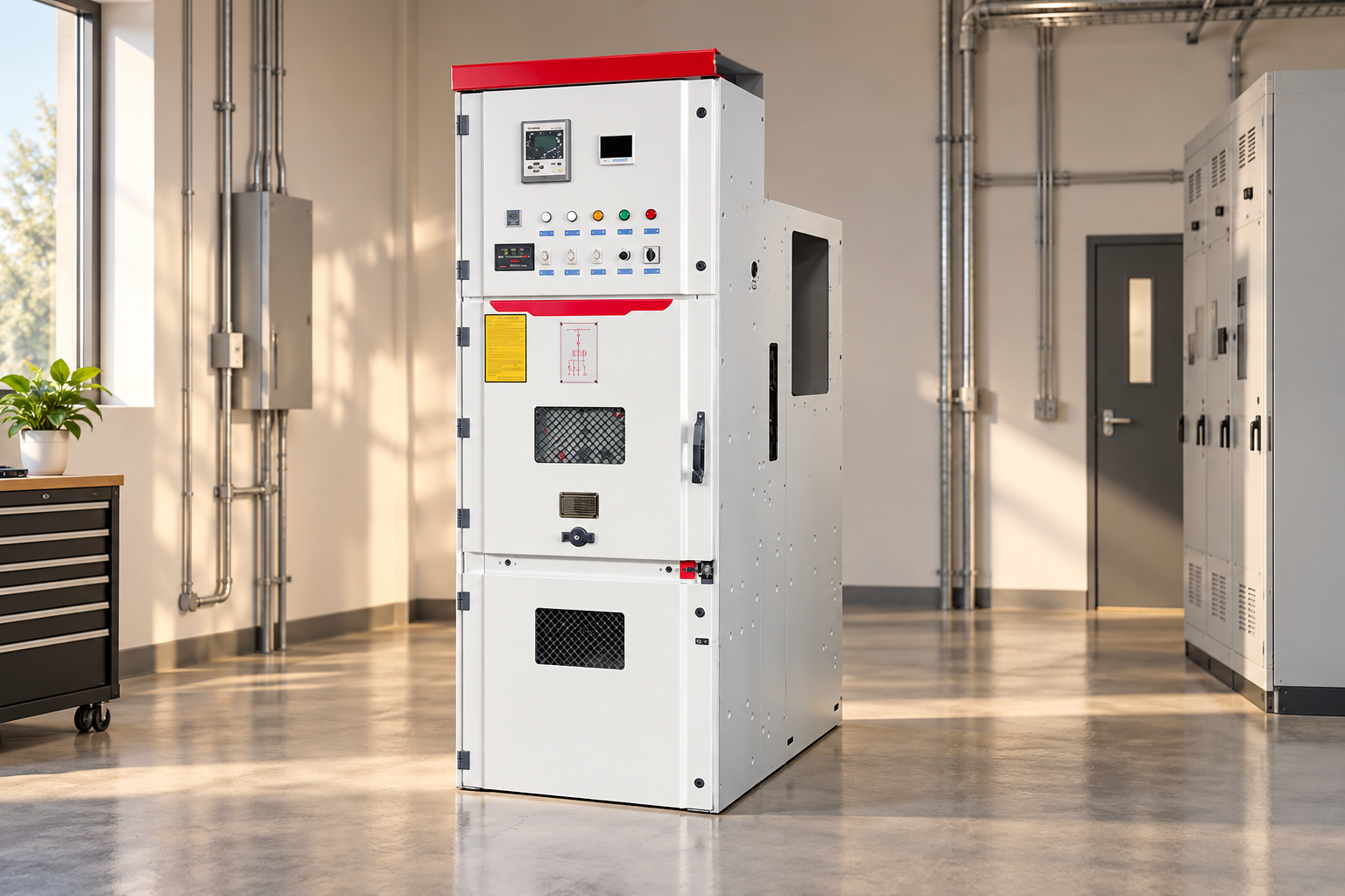
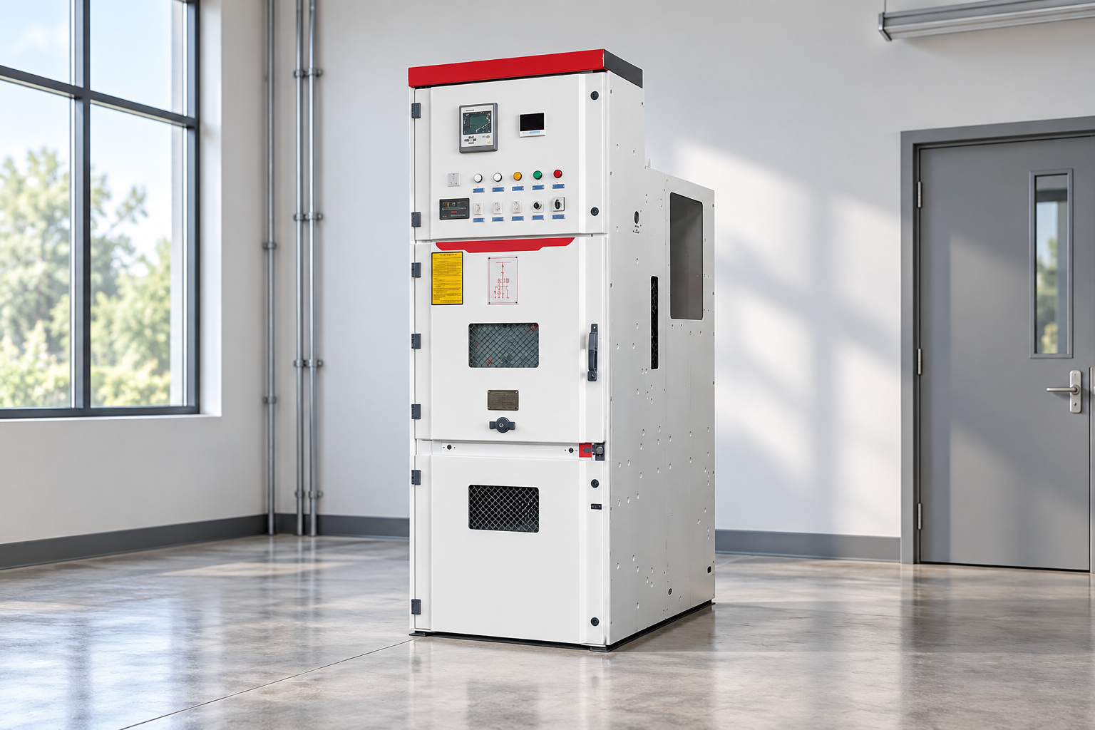
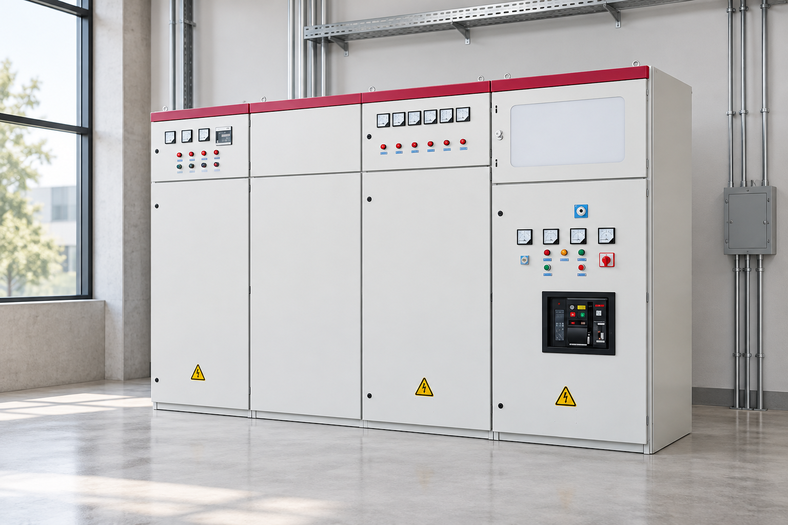
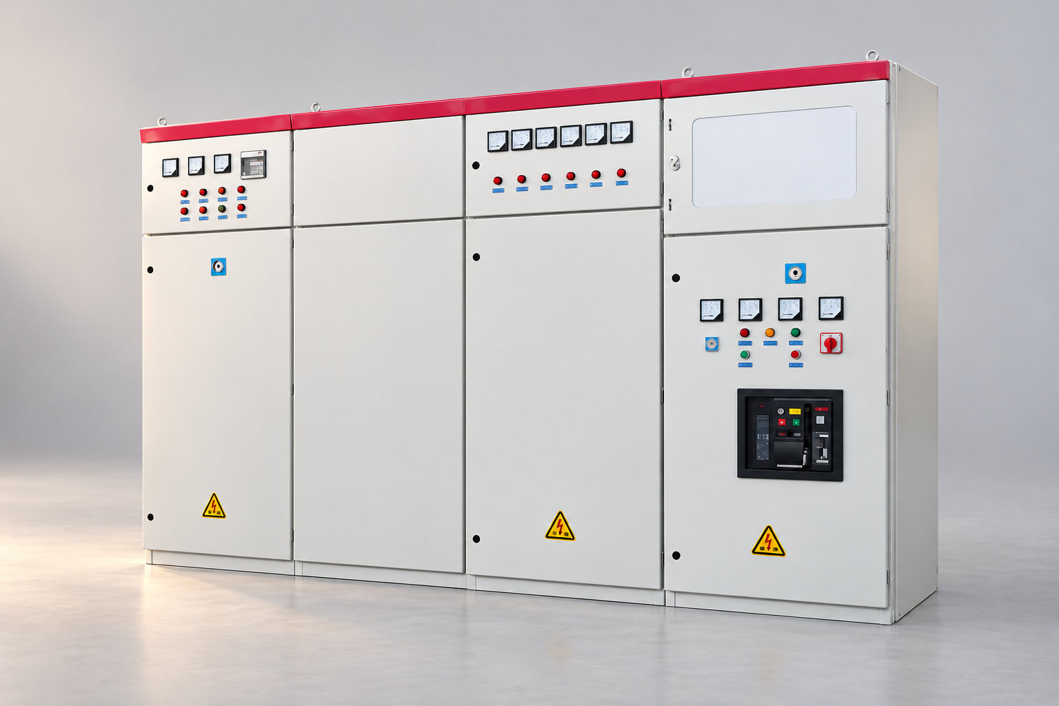
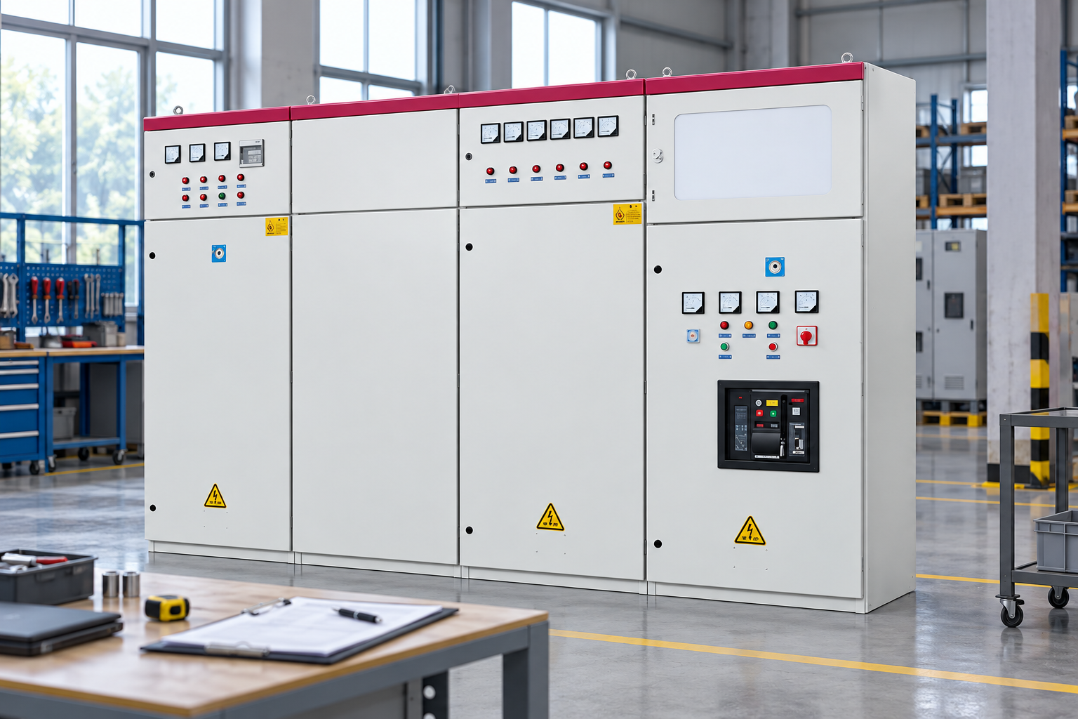
The LBAJI GGD reference illustrates a low-voltage assembly category for a procurement discussion. It does not establish a specific data center certification, topology or availability level. Ask for the exact proposed configuration and verify its relationship to the approved design. The product’s exterior can show enclosure arrangement, but it cannot prove independent supplies, transfer behavior or system-level fault isolation.
Review utility, generator and tie configurations
Identify which sources can feed each bus and under which conditions. Define normal tie positions, permitted parallel states and source-transfer requirements. If generators operate in a coordinated system, clarify the boundaries between generator controls and distribution controls. The supplier needs a controlled operating narrative, not only a one-line with several source symbols.
Consider restoration as well as failure. Returning from generator supply to utility supply can involve sequencing, synchronization or an interruption according to the design. Test plans should include the accepted return-to-normal sequence. Identify the response to a missing source-available signal or failed command. A transfer that works only when every control input is healthy may not support the required failure scenarios.
Assess fault duty in every permitted state
The available fault current and protective behavior can change between utility and generator operation and when sources are paralleled. The study should cover the states actually permitted by the operating philosophy. Request the required device and assembly ratings with matching evidence. Continuous-current capacity is one input, while interrupting and withstand duties need separate review.
Coordinate the equipment proposal with the system study rather than choosing a lineup first and hoping the numbers fit later. If the owner plans expansion, identify its study assumptions and the review needed before additional sources or loads are connected. A future tie or generator can alter duty even when the existing cabinets remain physically unchanged. Retain those assumptions in the handover file so later teams understand the design boundary.
Coordinate protection with selective isolation goals
Protection should detect and clear faults within the approved system limits while avoiding unnecessary loss of healthy paths where the design supports that objective. Define the coordination study, relay functions and ownership of final settings. A familiar relay brand or a large breaker rating does not establish the desired selectivity across the facility.
Review protection behavior for downstream UPS and distribution interfaces as well as main buses. Consider whether mode changes require different settings or logic, and how those changes are controlled. Keep equipment limits and safety requirements visible; availability goals cannot justify an unsuitable protection delay. Retain accepted configuration files and test evidence. Future replacements should trigger a review of the coordinated system rather than copying settings without checking the new device.
Examine auxiliary power and common dependencies
Trip, close, protection, indications and communications depend on auxiliary power and control arrangements. Identify those supplies on the architecture and consider their failure behavior. Two primary power paths may still share a control supply, controller, communication link or operating dependency. The required resilience assessment should include those shared elements rather than assuming independence from cabinet separation.
Specify what remains functional if a controller fails or communications are lost. Clarify local operation, manual recovery and alarms. Record any function that depends on another supplier’s system. Interface owners should agree signals, timing assumptions and accepted fail states. A responsibility matrix is especially useful where switchgear, generators, UPS equipment and the building management system are supplied under different contracts.
Make maintenance access part of the architecture
Review how an assembly, breaker or bus section can be isolated for planned work while the required load remains supplied. The design should state the allowed maintenance configuration and its remaining exposure to failures. A spare breaker or alternate path is useful only if the operating sequence and isolation boundaries make it usable under approved procedures.
Coordinate equipment room layout, access, shipping sections and replacement routes with the maintenance plan. Confirm that the proposed arrangement supports the necessary physical work. Do not assume a draw-out feature removes all electrical hazards or permits work in every state. Site procedures, equipment instructions and qualified assessment still apply. OSHA work practices provide useful U.S. safety context, while the facility requires its own approved methods and responsibilities.

Specify monitoring and remote control precisely
Monitoring should provide reliable information about sources, breaker states, loads and significant alarms. Define point names, units, scaling and quality indicators. Distinguish a stale communication value from a confirmed field state. Operators should know whether a displayed status is measured directly, derived from logic or unavailable. That distinction can affect decisions during a failure.
If remote control is included, define permissions, local and remote modes, interlocks and the response to lost communications. Agree cybersecurity requirements with the owner’s responsible team. Commissioning should verify actual values and command behavior, not merely establish that a connection exists. Retain point lists, configuration versions and test records so changes in the monitoring platform do not silently alter the accepted electrical meaning.
Plan factory and integrated site acceptance
Factory acceptance can verify the ordered assembly and agreed functions using a defined setup. It should identify simulated sources and interfaces. Integrated site testing then addresses installed equipment, real controls and the accepted operating sequences. Distinguish these scopes in the procurement documents. A successful factory simulation cannot establish that the complete data center responds correctly to every specified failure.
Agree the witness plan, acceptance criteria and method for closing findings before the test date. Include restoration, manual recovery and communication-loss cases where they are within the approved scope. The final report should connect results to equipment identities, drawing revisions and configurations. A test log with clear expected outcomes is more useful than a general statement that the lineup was “fully tested.”
Prepare expansion and handover documents
Reserve capacity or space only through a defined design assumption. Future feeders, source additions and control changes should have a stated review process. Spare positions do not automatically establish capacity for unknown loads. The owner needs to know what can be added within the current verified scope and what requires renewed engineering or evaluation.
The handover file should include as-built drawings, settings, accepted logic, test results, maintenance instructions and interface ownership. Keep the operating-state matrix current as the facility changes. The value of the switchgear is its fit within an understood and verified architecture. Avoid unsupported promises about uptime or tier status; document the actual functions and evidence the owner can use in the facility’s broader acceptance process.
Resilience review worksheet
| Review area | Scenario to evaluate | Evidence to request |
|---|---|---|
| Primary paths | One source or bus section unavailable | Approved one-line and operating-state matrix |
| Dòng cắt sự cố | Utility, generator and permitted parallel operation | System study and matching equipment ratings |
| Bảo vệ | Fault on one downstream path | Accepted coordination study and settings |
| Auxiliary systems | Control supply or communications lost | Dependency diagram and defined fail behavior |
| Bảo trì | A critical device isolated for work | Maintenance configuration and physical-access review |
| Integration | Failure and return-to-normal sequences | Factory scope and integrated site test records |
Các câu hỏi thường gặp
Does two-incomer switchgear provide redundancy?
It can support an alternative power arrangement, but redundancy depends on the complete system and its shared dependencies. Review sources, buses, controls, downstream paths and permitted operating states. Confirm what happens during failures and maintenance. A component count or an A/B label alone cannot establish the resilience of the entire facility.
Can switchgear determine the data center tier?
A facility-level classification depends on more than an individual electrical assembly. This article does not assign a tier to a product or architecture. The owner should use the applicable assessment process and supporting evidence. A supplier can document equipment functions and tests, but a catalogue description should not be treated as a facility certification.
Why do generator-mode protection checks matter?
Source characteristics and available fault current can differ from utility operation. Protective behavior therefore needs review for the allowed operating configurations. Ask the responsible engineer to define the study and accepted settings. A factory test of relay outputs does not by itself prove system-level coordination under the actual generator supply conditions.
Does factory acceptance prove the complete transfer sequence?
It proves only what the agreed setup and procedure demonstrate. Sources, generator controls, UPS interfaces and site communications may be simulated or absent. Identify those boundaries and plan integrated testing after installation. Retain both reports so the owner can distinguish assembly acceptance from evidence about the complete operating sequence.
What should a data center switchgear RFQ prioritize?
Prioritize the architecture, operating states, equipment duties, protection, auxiliary supplies and interface responsibilities. Include maintenance access, communications, verification, factory tests and integrated site acceptance. Define future expansion assumptions and handover records. Those inputs make proposals comparable and reduce the risk that an attractive equipment feature masks an unresolved system dependency.
Related LBAJI resources
LBAJI GGD Low-Voltage Switchgear. switchgear fundamentals. Hướng dẫn kiểm tra thiết bị chuyển mạch. switchgear maintenance checklist.
Technical sources
Use these references for the relevant equipment and work-practice scope. Confirm the edition and project requirements with the responsible engineer.
- IEC metal-enclosed AC switchgear scope
- OSHA electrical work practices
- IEC low-voltage assembly general rules
Further viewing
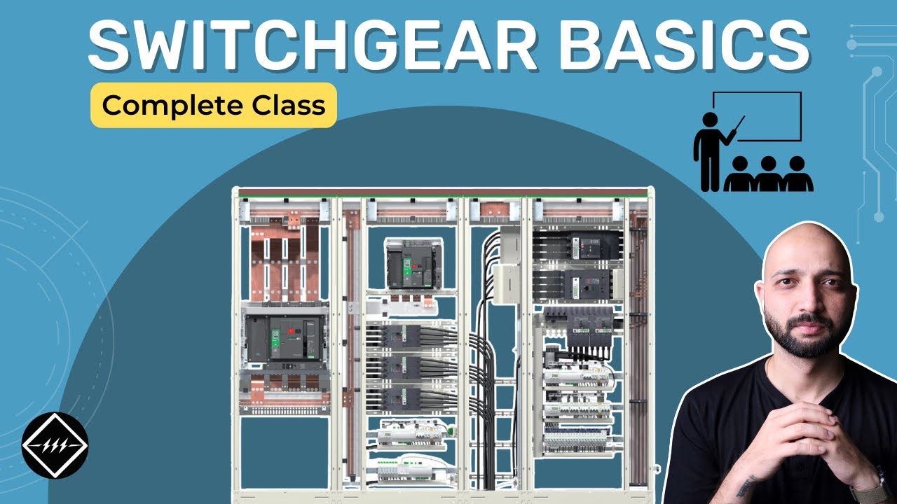
Gaurav J – TheElectricalGuy — Switchgear Basics: Complete Beginner’s Guide | TheElectricalGuy. This independent educational video provides background principles; it does not specify LBAJI equipment ratings or replace a project procedure.