Industrial switchgear systems distribute power to production equipment while providing switching, protection, isolation and control. Their design starts with the plant’s loads, sources, fault conditions and operating needs, rather than a catalogue cabinet size. Motors, variable-speed drives, process equipment and backup generators can create different requirements within the same factory. This guide explains how to prepare a system brief, choose an arrangement and review the interfaces before procurement. It addresses the distribution system as a coordinated whole; individual product ratings, operating procedures and protection settings still require project-specific engineering and verified manufacturer information.
Map the plant’s normal and abnormal operating states
Begin with a load schedule grouped by process, voltage and required availability. Identify loads that may stop without major consequences, loads needed for a controlled shutdown and loads that must remain supplied during a source failure. Record operating hours, start-up sequences and future expansion assumptions. A single total kilowatt figure hides the practical differences between a workshop, a continuous process line and a safety-related auxiliary system.
Then describe normal supply, planned maintenance and credible failures. Ask what happens if an incoming feeder, transformer, bus section or generator becomes unavailable. The system arrangement should allow the plant to respond through an approved operating philosophy. A spare feeder is useful capacity, but it does not automatically provide an alternative source. Write each permitted source and tie configuration explicitly before designing the interlocking and protection logic.
Distinguish medium-voltage distribution from utilization circuits
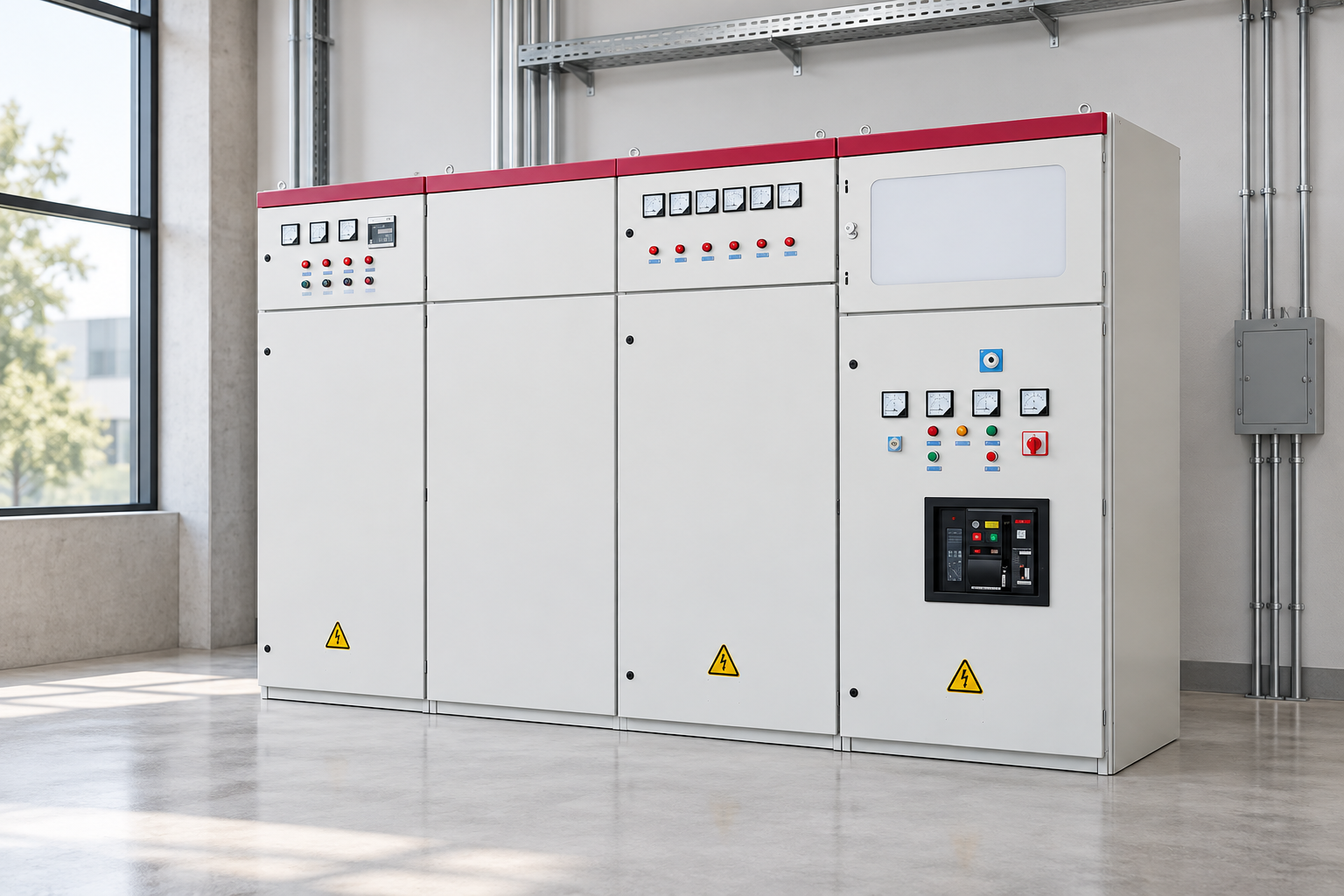
Medium-voltage equipment may receive the utility supply and feed transformers or large motors. Low-voltage assemblies then distribute power to process areas and downstream control equipment. A motor control center serves a different function from the main distribution lineup, even if both use floor-standing cabinets. Define the boundaries between these assemblies, including cable interfaces, protection coordination and control signals.
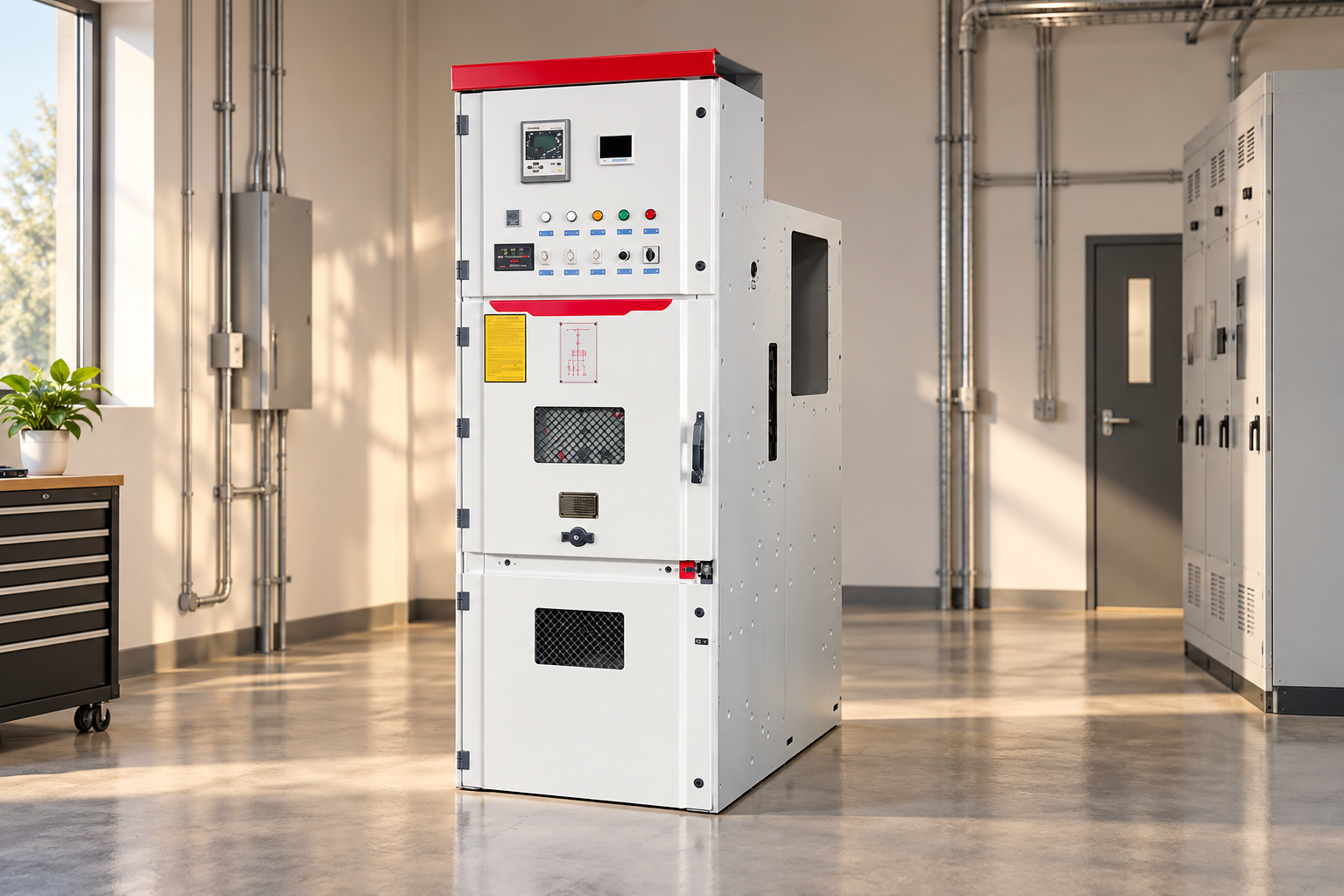
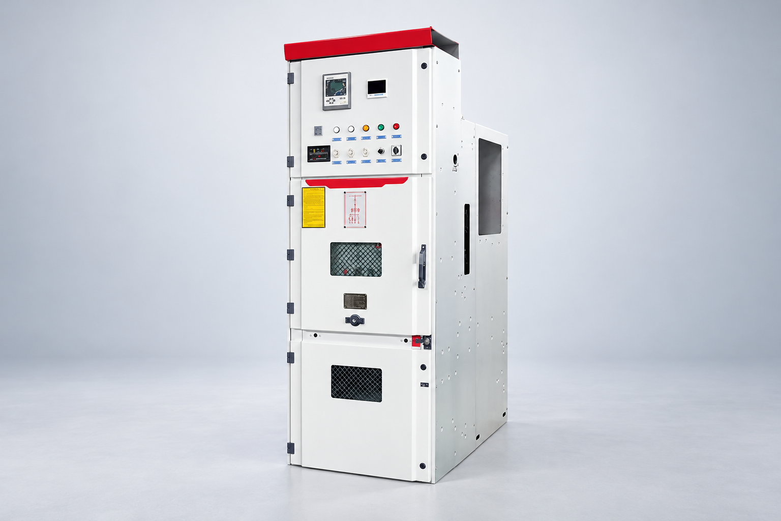
An LBAJI KYN28A-12 product can illustrate a medium-voltage metal-clad equipment category. It cannot establish the suitability of an entire industrial system from its exterior appearance. Request the actual voltage and insulation ratings, continuous current, fault duties, bay functions and environmental assumptions. Coordinate these with the downstream transformer and low-voltage distribution design. Equipment class and project duty should drive the specification, rather than a preferred enclosure photograph.
Develop the source and bus arrangement
A single-source arrangement can be appropriate where interruptions are acceptable and maintenance can be scheduled. A sectionalized bus or alternative source may improve operational flexibility, but it introduces additional switching states and responsibilities. Compare how each arrangement behaves during faults, maintenance and restoration. Define whether ties are normally open or closed and whether any sources may operate in parallel.
Avoid assuming that more breakers always mean a better system. Additional devices can create complexity, common control dependencies and more maintenance tasks. The useful question is whether the arrangement supports the plant’s required states with understandable protection and operating procedures. Record the intended sequence for transferring loads and returning to normal operation. Review it with operations staff before the control scheme is frozen.
Study load current, motor starting and fault duty
Continuous current sizing needs a realistic load model and applicable design requirements. Consider operating diversity, starting conditions, ambient environment and planned additions. Large motors can create starting demands that are not represented by their normal running current. Drives introduce their own input characteristics and harmonic considerations. Collect manufacturer data and coordinate the assessment with the electrical system study.
Fault-duty assessment must include the relevant sources and operating configurations. Utility supply, generators and motor contribution can change the conditions seen by a particular bus or breaker. Do not use a familiar current rating as a substitute for interrupting or withstand ratings. The engineer should verify the required duties and compare them with assembly and device evidence. Record the assumptions so a later source change triggers review rather than silently invalidating the design.
Coordinate protection with the process needs
Protection should clear faults while limiting unnecessary interruption of healthy circuits where the design permits. Coordination is a system task involving upstream and downstream devices, equipment limits and operating configurations. Request a defined study scope and responsibility for settings. A relay installed in the cabinet does not prove that its functions have been selected or coordinated correctly.
Review what the process requires during a fault and recovery. A rapid trip may protect equipment but stop a critical process, while an inappropriate delay may exceed equipment limits. These tradeoffs need engineering and owner approval. Document settings, configuration files and change control. Site operators should know which alarms indicate a maintenance concern and which require an immediate controlled response, using the approved instructions rather than general internet advice.
Specify interlocks and auxiliary power
Interlocks help prevent prohibited operating combinations, such as closing a tie in an unapproved source configuration. Define the desired behavior in plain operating-state terms before selecting mechanical, electrical or software methods. Identify the response to a failed signal, loss of control power or equipment in a test position. A drawing that merely says “interlocked” leaves too much interpretation for assembly and commissioning.
Auxiliary power supports trip, close, indication, protection and communication functions. List the required supply sources and the expected behavior when the main bus is unavailable. Confirm device requirements and any stored-energy or backup arrangements. Review these dependencies alongside the source-transfer design. Two power paths that rely on one unexamined control supply may not provide the resilience assumed in a production planning discussion.
Address the industrial environment
Factories may expose equipment to dust, moisture, corrosive atmospheres, vibration or temperature extremes. Describe actual conditions, including nearby processes and cleaning practices. Select enclosure and environmental provisions from the declared product scope and project requirements. An indoor lineup cannot be assumed suitable for outdoor service simply because it has solid doors or a familiar paint coating.
Plan access for cable termination, inspection, device replacement and safe isolation. Coordinate equipment room layout with installation and maintenance requirements, fire provisions and ventilation assumptions. Avoid placing a production obstruction where a future breaker removal or cable inspection needs space. For U.S. workplaces, OSHA electrical work practices provide relevant safety context. The project still needs competent review of applicable local rules and a site-specific procedure.
Connect monitoring without making controls ambiguous
Metering and communications can help a plant understand loading, energy use and equipment status. Define the information needed by operations, maintenance and energy management rather than collecting every available point. Specify point names, units, alarm priorities and the difference between an indication and a command. A displayed breaker status should clearly identify its source and any communication failure condition.
If remote control is included, define permissions, local and remote modes, interlocks and the behavior after lost communications. Coordinate electrical controls with the plant’s cybersecurity and operational policies. Commissioning should verify both values and meaning: a current value scaled incorrectly can look plausible while misleading operators. Retain the accepted point list, test records and final configuration alongside the electrical drawings.
Test factory functions and site integration separately
Factory checks can verify the ordered assembly and agreed control functions under defined test conditions. Site commissioning then checks transport condition, installation interfaces and integration with real sources and loads. Prepare both scopes before equipment arrives. Distinguish a simulated transfer from a site test using the actual generator, and identify any functions that cannot be demonstrated fully at the factory.
The final handover should include as-built drawings, test results, approved settings, operation instructions and responsibility for future changes. Equipment expansion, a new generator or a major drive installation may require renewed study. Build a management process that keeps the one-line and settings current. A coordinated industrial system remains useful because its operating information follows the physical plant, rather than becoming an obsolete folder after commissioning.
Industrial system review table
| Design input | Why it changes the system | Review output |
|---|---|---|
| Process criticality | Determines acceptable interruption and recovery needs | Load groups and approved failure scenarios |
| Sources and ties | Changes power paths and fault conditions | Operating philosophy and permitted states |
| Motors and drives | Affects starting, loading and waveform assessment | Load model and equipment data |
| Bảo vệ | Connects device operation to equipment limits | Approved coordination study and settings |
| Môi trường | Influences enclosure, access and maintenance provisions | Site conditions and layout review |
| Controls | Creates auxiliary power and communication dependencies | Logic narrative, point list and functional tests |
Các câu hỏi thường gặp
Is industrial switchgear the same as a motor control center?
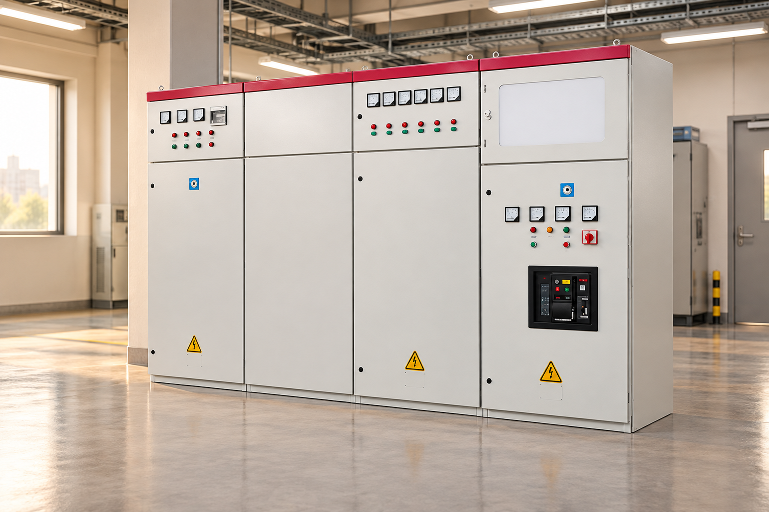
They can be connected within the same plant but have different functions. Main switchgear distributes and protects power at a system level, while a motor control center organizes motor-related control and protection. Define the boundary and coordinate upstream and downstream devices. Do not select one assembly solely because its cabinet resembles the other in a photograph.
Does a second incoming feeder guarantee uninterrupted production?
No. The second feeder must be usable within the approved source and protection design. Shared upstream infrastructure, common bus sections, control supplies and transfer conditions can still affect both paths. Review failures and maintenance states explicitly. The owner should specify acceptable interruption and recovery behavior, then verify the proposed arrangement against those needs.
Why must generators be included in the fault study?
A generator can change the available fault current and the behavior of protective devices in an alternative operating state. The relevant result depends on the actual generator, system connections and other contributing sources. Ask the engineer to assess the configurations permitted by the operating philosophy. Do not assume utility-mode settings automatically produce suitable generator-mode performance.
Can monitoring replace inspection and maintenance?
Monitoring can identify loading patterns, alarms and some abnormal conditions, but it does not verify every mechanical connection or insulation condition. Use it as part of an approved maintenance program. Confirm sensor scope, data quality and alarm meaning. Equipment instructions, operating history and qualified assessment should guide maintenance actions rather than a dashboard status alone.
What should an industrial switchgear RFQ include?
Include the load schedule, single-line, source states, fault-duty requirements, environment, bay schedule and interface drawings. Identify engineering and certification responsibilities, protection functions, auxiliary power and communications. Request deviations, factory tests, delivery milestones and handover documents. Clear inputs allow suppliers to quote the same system and make unresolved assumptions visible before procurement.
Related LBAJI resources
LBAJI KYN28A-12 Metal-clad Withdrawable AC Switchgear. switchgear fundamentals. Hướng dẫn kiểm tra thiết bị chuyển mạch. switchgear maintenance checklist.
Technical sources
Use these references for the relevant equipment and work-practice scope. Confirm the edition and project requirements with the responsible engineer.
Further viewing
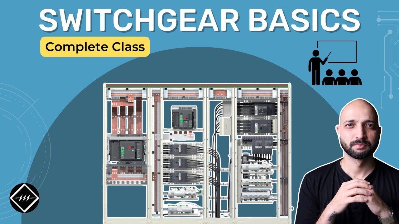
Gaurav J – TheElectricalGuy — Switchgear Basics: Complete Beginner’s Guide | TheElectricalGuy. This independent educational video provides background principles; it does not specify LBAJI equipment ratings or replace a project procedure.