A switchgear contact resistance test measures the resistance of a defined conductive path so that engineers can identify unusual connections, compare equivalent phases and track changes against a reliable baseline. The reading is useful only when the test boundary, instrument arrangement, equipment condition and acceptance basis are recorded. A small number by itself does not prove that a complete assembly is fit for service. For procurement and maintenance teams, the practical goal is a repeatable result tied to the supplied equipment and an agreed decision process, rather than an unsupported universal micro-ohm limit.
Define exactly what the measurement includes
A switchgear assembly contains several possible measurement paths. A reading across a closed circuit breaker may include its terminals, internal conductor joints and switching contacts. A measurement across a withdrawable assembly may also include disconnecting contacts. A busbar joint measurement has a different boundary again. These results cannot automatically be compared with each other simply because the instrument displays the same unit.
Start the inspection record with a drawing or clearly described pair of connection points. Identify the phase, equipment serial number, breaker position and included interfaces. State whether the breaker was removed, inserted or connected through an approved test arrangement. For a new project, agree these boundaries before the factory witness visit so that the manufacturer and purchaser collect comparable evidence.
Keep testing within a controlled isolation procedure
Contact resistance testing is a task for appropriately qualified personnel using approved equipment instructions and a site electrical safety procedure. The assembly must be placed in the required safe state, isolated from relevant energy sources and checked under the applicable work-control process. A low-resistance instrument is not a voltage detector and does not establish safe isolation.
Stored energy, auxiliary supplies, connected cables and parallel paths require explicit consideration. Do not assume that opening the main breaker removes every hazard. The work plan must identify who authorizes access, establishes protective measures and restores the equipment. This article explains how to evaluate the test record; it does not prescribe a live-work method or replace an equipment-specific procedure.
Why a four-terminal arrangement matters
In a two-wire resistance measurement, the test leads and their connections contribute to the displayed result. When the resistance of interest is very small, that contribution can overwhelm the quantity being assessed. A four-terminal or Kelvin arrangement separates the current-injection connections from the voltage-sensing connections so that lead voltage drops outside the sensing boundary have less influence on the calculated resistance.
The basic relationship is resistance equals measured voltage divided by injected current. This familiar relationship does not make every setup equivalent. Sensing positions, connection stability, instrument capability and the behavior of the equipment under test remain important. Use the instrument manufacturer’s instructions for connection order and operating conditions, and retain enough setup information for a later team to reproduce the measurement.
Choose the acceptance basis before collecting readings
A defensible acceptance decision starts with the supplied equipment documentation and the contractually applicable test requirements. An assembly rating, a generic checklist or an unrelated breaker manual does not establish a valid limit for a particular contact path. Where the manufacturer provides a limit, verify that it applies to the exact model, configuration, measurement boundary and test conditions.
If no suitable limit is available, ask the responsible engineer and manufacturer to define the assessment basis before declaring a pass. Equivalent phase comparisons and historical trends can identify a condition worth investigating, but they are not a substitute for an agreed limit. Record uncertainty honestly: a measurement can be valid while the acceptance decision remains pending.
Bối cảnh tham khảo: IIT Kharagpur Virtual Labs: Kelvin double bridge and low resistance measurement. Danh sách kiểm tra chất lượng gốc này tổ chức các quyết định của dự án; nó không phải là một tiêu chuẩn được sao chép hoặc thay thế cho các tiêu chí đã được phê duyệt.
| Record item | Tại sao điều đó quan trọng | What a useful record contains |
|---|---|---|
| Equipment identity | Prevents comparison with a different assembly | Model, serial number, phase and drawing revision |
| Measurement boundary | Determines the interfaces included | Current and sensing connection locations and breaker position |
| Instrument arrangement | Supports repeatability | Instrument identity, calibration status and applicable setup instructions |
| Conditions | Separates equipment change from test variation | Equipment state, relevant temperature and preceding operations |
| Assessment basis | Makes the decision traceable | Applicable manufacturer criteria, project requirements and reviewer |
| Follow-up | Prevents unexplained outliers being accepted | Investigation, authorized action and repeat-test reference |
Compare phases without hiding configuration differences
A comparison between phases is most useful when the conductive paths and test conditions are genuinely equivalent. Different terminal arrangements, conductor lengths or included joints can produce different expected results. The comparison record should state why the phases are considered comparable, rather than assuming symmetry from the front view of the enclosure.
When one phase differs noticeably, first verify the setup and boundaries. Check whether the sensing points, mechanical position and connection quality were consistent. If the difference persists, document it for engineering investigation. Do not average away an outlier or repeatedly change the test arrangement until a preferred number appears. Preserve the initial and repeat readings with an explanation of what changed.

Use a baseline that can be reproduced
A factory baseline can be valuable during commissioning and future maintenance if its method is sufficiently documented. A spreadsheet containing only three resistance values is difficult to use when the field team measures a different path or uses different operating conditions. Request the original report and connection description, not just a summary certificate.
A good baseline identifies the equipment before shipment, the tested positions and the assessment criteria. At site, record any assembly work, cable connection work, transport damage or replacement components that could affect comparability. If the site test includes interfaces absent from the factory test, keep the results as separate baselines rather than forcing a direct numerical comparison.
Treat temperature and operating history as context
Conductor resistance depends on material and temperature, while contact behavior can also be affected by surface condition and mechanical contact pressure. Record the temperature information required by the approved procedure. A room thermostat reading may not represent the temperature of equipment recently carrying load, especially when cooling time varies between inspections.
Do not apply a generic temperature correction to a complete contact path unless the manufacturer or responsible engineer supports that method. A mixed path may contain several materials and contact interfaces. Similarly, if the approved procedure calls for specified mechanical operations before testing, record those operations. Undocumented conditioning can make an apparent improvement difficult to interpret later.
Investigate abnormal results systematically
An unusual reading may arise from an unstable test connection, incorrect sensing location, an unintended parallel path or a real defect. The first response should be a controlled investigation that distinguishes these possibilities. Save the original result, review the arrangement and repeat only under an authorized, documented method. This creates evidence rather than a collection of unexplained numbers.
If a physical connection needs attention, use the supplied assembly instructions and an approved work order. Do not loosen, polish or retighten a joint simply to obtain a lower reading. Surface treatments, contact designs and torque requirements differ. Unauthorized intervention can damage the connection, invalidate the baseline or conceal the reason for the initial result.

Distinguish resistance testing from thermal inspection
A contact resistance test and an operating thermal survey answer related but different questions. The resistance test measures a defined path under controlled test conditions. A thermal survey observes temperature patterns under the actual loading and environmental conditions present during the inspection. Neither result automatically proves the other will be satisfactory.
Use the two methods as complementary evidence where the maintenance program requires them. A resistance result does not justify energizing equipment with an unresolved mechanical or insulation defect. A quiet thermal image under light load does not demonstrate that every connection is sound. Record loading, access restrictions and other limitations when linking reports across the two methods.
Specify the evidence in a purchase order
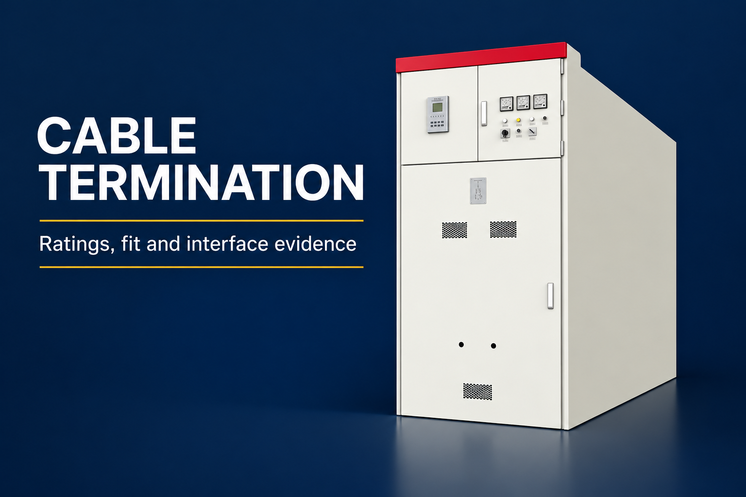
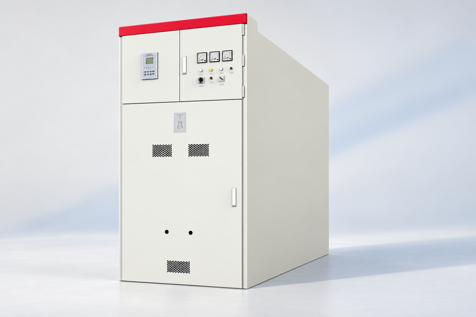
A buyer should request a test schedule that identifies which conductive paths are covered and which are excluded. For an enclosed medium-voltage assembly, ask the supplier to explain whether the delivered report covers breaker contacts, disconnecting interfaces, main circuit connections or another defined boundary. The exterior product photograph cannot answer this question.
For LBAJI KYN61 equipment, the product page establishes the relevant assembly family, while the project drawings and supplied test documentation must establish the actual configuration. Request the agreed standard edition, report format, witness points and treatment of deviations. Avoid writing an arbitrary resistance limit into a purchase specification without confirming its technical basis and applicability.
Close the test with a documented decision
The final report should connect each result to an assessment and a responsible reviewer. A complete set includes the raw readings, method, equipment identification, acceptance basis and any deviation or corrective-action record. If a result is unresolved, label it pending and identify what evidence is needed. A signed cover sheet should not hide exceptions in an appendix.
Before returning equipment to service, complete the applicable restoration and authorization process. Testing can introduce temporary leads, changed positions or disconnected auxiliary circuits that must be controlled. Handover should state the equipment condition and any remaining restrictions, making clear that a resistance measurement is one part of the overall readiness assessment.
Các câu hỏi thường gặp
What does a switchgear contact resistance test measure?
It measures the resistance of a defined conductive path, which may include switching contacts, joints or disconnecting interfaces. The connection points and included components must be recorded before the result can be interpreted.
Is there one acceptable resistance value for every breaker?
No. Use criteria applicable to the supplied model, measurement boundary and test conditions. A generic value copied from another product or checklist is not an adequate acceptance basis.
Why use a four-terminal resistance instrument?
Separating current injection from voltage sensing reduces the influence of lead and connection voltage drops outside the sensing boundary. Correct setup and the instrument instructions remain essential.
Can phase comparison replace manufacturer criteria?
Equivalent phase comparisons can highlight unusual behavior, but configuration differences must be considered. They support investigation and trending rather than automatically replacing the agreed acceptance requirements.
Does a good resistance result prove that switchgear is ready to energize?
No. The result addresses a particular conductive path under the recorded conditions. Insulation, mechanical operation, protection, safety controls and the complete commissioning requirements need their own checks.
Nguồn thông tin kỹ thuật và thiết bị liên quan
Các trang danh mục tiêu chuẩn xác định phạm vi tài liệu; việc tuân thủ và chấp nhận yêu cầu các tài liệu đầy đủ áp dụng và việc đánh giá kỹ thuật dự án.
- IIT Kharagpur Virtual Labs: Kelvin double bridge and low resistance measurement
- Phạm vi của thiết bị chuyển mạch AC có vỏ bọc bằng kim loại theo tiêu chuẩn IEC 62271-200
- UK HSE HSG85: Electricity at work, safe working practices
- LBAJI KYN61-40.5 Thiết bị chuyển mạch có thể tháo rời bằng thép không gỉ
- Những nguyên tắc cơ bản về thiết bị điều khiển
- Kiểm tra và thử nghiệm thiết bị chuyển mạch
- switchgear thermal inspection evidence
Học tập nâng cao: kiến thức chuyên môn
This independent educational video explains the measurement principles or equipment background discussed above. It does not demonstrate a safe work procedure for the specific assembly. Source: NPTEL IIT Kharagpur.