


Overview
S □ -M series three-phase oil-immersed power transformer is a new product of national science and technology. developed on the basis of new power product structure design. The main idea of the design is to meet the reliability of the product and improve the performance of the product. According to the actual situation of the new power product,some loss coefficients and structures are re-adjusted in the design to make the loss design value more in line with the real side value. At the same time,the optimized design is carried out to determine the copper and iron ratio reasonably,so that the material cost is lowest and the structure is more reasonable.
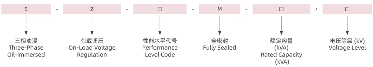
Model Meaning
Iron Core
Adopt high-quality,high-performance silicon steel sheet with high magnetic permeability and low loss to reduce no-load loss
Windings And body
Adopt high-quality,high-performance silicon steel sheet with high magnetic permeability and low loss to reduce no-load loss
Structure
Products with 630kvA and above adopt a new spiral type for low pressure. Body assembly summarizes the mature experience of new power transformers. After assembly,the body becomes a solid whole, ensuring that the product meets the electrical performance and mechanical strength requirements in case of sudden short circuits. This series of products has a fully sealed structure,which ensures the isolation of transformer oil from the outside air,prevents the aging of the oil,and improves the operating reliability of the transformer.
The oil tank adopts a corrugated oil tank: a long hole is opened on the bottom and bottom wall of the tank to promote the circulation of oil in the corrugated sheet. This fuel tank has simple process,high mechanical strength,improved oil fluidity and heat dissipation capacity,good welding effect and is not easy to leak.
Appearance and installation dimensions
S11-M OIL-IMMERSED POWER TRANSFORMER
![]()
S13-M OIL-IMMERSED POWER TRANSFORMER
![]()
S20-M OIL-IMMERSED POWER TRANSFORMER
![]()
S22-M OIL-IMMERSED POWER TRANSFORMER
![]()
Note: The dimensions and weight provided are only for reference in the design and selection, and the final dimensions and weight are subject to our company’s product drawings.
Technical Parameters
S11-M Oil-Immersed Power Transformer
| Rated Capacity (KVA) |
Voltage Combination And Tap Range (kV) |
Connection Groups | NO Load Loss (W) |
Load Loss (w) |
NO Load Current (%) |
Short Circuit Impedance (%) |
Overall Size | Gauge | Weight (kg) | ||||
| High Pressure (kV) |
Tapping Range
% |
Low Pressure (kV) | Length (L) |
Width (B) |
Height (H) |
Horizontal ×Vertical a × b |
|||||||
| S11-M-30 | 6 6.3 10 10.5 11 |
±5% ±2×2.5% |
0.4 | Dyn11
Yyn0 |
100 | 630/600 | 1.5 | 4.00% | 690 | 510 | 920 | 400×400 | 275 |
| S11-M-50 | 130 | 910/870 | 1.3 | 730 | 510 | 960 | 400×450 | 340 | |||||
| S11-M-63 | 150 | 1090/1040 | 1.2 | 750 | 550 | 1000 | 400×450 | 385 | |||||
| S11-M-80 | 180 | 1310/1250 | 1.2 | 790 | 620 | 1020 | 400×450 | 450 | |||||
| S11-M-100 | 200 | 1580/1500 | 1.1 | 790 | 700 | 1040 | 550×550 | 520 | |||||
| S11-M-125 | 240 | 1890/1800 | 1.1 | 840 | 800 | 1070 | 550×550 | 625 | |||||
| S11-M-160 | 280 | 2310/2200 | 1 | 1070 | 670 | 1130 | 550×550 | 695 | |||||
| S11-M-200 | 340 | 2730/2600 | 1 | 1140 | 750 | 1140 | 550×550 | 795 | |||||
| S11-M-250 | 400 | 3200/3050 | 0.9 | 1200 | 800 | 1190 | 550×550 | 955 | |||||
| S11-M-315 | 480 | 3830/3650 | 0.9 | 1300 | 860 | 1210 | 550×550 | 1085 | |||||
| S11-M-400 | 570 | 4520/4300 | 0.8 | 1380 | 900 | 1240 | 660×660 | 1290 | |||||
| S11-M-500 | 680 | 5410/5100 | 0.8 | 1450 | 950 | 1300 | 660×660 | 1590 | |||||
| S11-M-630 | 810 | 6200 | 0.6 | 4.50% | 1500 | 970 | 1360 | 660×660 | 1850 | ||||
| S11-M-800 | 980 | 7500 | 0.6 | 1660 | 1140 | 1400 | 660×660 | 2210 | |||||
| S11-M-1000 | 1150 | 10300 | 0.6 | 1690 | 1190 | 1530 | 660×660 | 2570 | |||||
| S11-M-1250 | 1360 | 12000 | 0.5 | 1760 | 1230 | 1600 | 820×820 | 3115 | |||||
| S11-M-1600 | 1640 | 14500 | 0.5 | 1800 | 1250 | 1660 | 820×820 | 3520 | |||||
| S11-M-2000 | 1940 | 18300 | 0.4 | 5.00% | 2070 | 1270 | 1880 | 820×820 | 4375 | ||||
| S11-M-2500 | 2290 | 21200 | 0.4 | 2180 | 1320 | 1970 | 820×820 | 4950 | |||||
Note 1: For transformers with a rated capacity of 500kvA or less,the load loss values above the slash in the table apply to the Dyn11 or Yzn11 connection group,and the load loss values below the slash line apply to the Yyn0 connection group.
Note 2: When the transformer annual average load rate is between 35% and 40%,the loss value in the table can be used to obtain the highest operating efficiency.
S13-M Oil-Immersed Power Transformer
| Rated Capacity (KVA) |
Voltage Combination And Tap Range (kV) |
Connection Groups |
NO Load Loss (W) |
Load Loss (w) |
NO Load Current (%) |
Short Circuit Impedance (%) |
Overall Size | Gauge | Weight (kg) |
||||
| High Pressure (kV) |
Tapping Range % |
Low Pressure (kV) |
Length (L) |
Width (B) |
Height (H) |
Horizontal × Vertical a × b |
|||||||
| S13-M-30 | 6 6.3 10 10.5 11 |
±5% ±2×2.5% |
0.4 | Dyn11
Yyn0 |
80 | 630/600 | 1.5 | 4.00% | 695 | 490 | 860 | 400×400 | 260 |
| S13-M-50 | 100 | 910/870 | 1.3 | 725 | 520 | 955 | 400×450 | 365 | |||||
| S13-M-80 | 130 | 1310/1250 | 1.2 | 770 | 565 | 985 | 400×450 | 465 | |||||
| S13-M-100 | 150 | 1580/1500 | 1.2 | 800 | 595 | 1000 | 550×550 | 545 | |||||
| S13-M-125 | 170 | 1890/1800 | 1.1 | 815 | 670 | 1010 | 550×550 | 585 | |||||
| S13-M-160 | 200 | 2310/2200 | 1.1 | 1015 | 645 | 1055 | 550×550 | 695 | |||||
| S13-M-200 | 240 | 2730/2600 | 1 | 1020 | 650 | 1115 | 550×550 | 810 | |||||
| S13-M-250 | 290 | 3200/3050 | 1 | 1140 | 730 | 1120 | 550×550 | 930 | |||||
| S13-M-315 | 340 | 3830/3650 | 0.9 | 1195 | 785 | 1175 | 550×550 | 1075 | |||||
| S13-M-400 | 410 | 4520/4300 | 0.9 | 1265 | 855 | 7795 | 660×660 | 1255 | |||||
| S13-M-500 | 480 | 5410/5100 | 0.8 | 1325 | 915 | 1240 | 660×660 | 1435 | |||||
| S13-M-630 | 570 | 6200 | 0.8 | 4.50% | 1465 | 960 | 1295 | 660×660 | 1880 | ||||
| S13-M-800 | 700 | 7500 | 0.6 | 1515 | 995 | 1340 | 660×660 | 2145 | |||||
| S13-M-1000 | 830 | 10300 | 0.6 | 1605 | 1095 | 1460 | 660×660 | 2455 | |||||
| S13-M-1250 | 970 | 12000 | 0.5 | 1685 | 1145 | 1485 | 820×820 | 2840 | |||||
| S13-M-1600 | 1170 | 14500 | 0.5 | 1775 | 1225 | 1580 | 820×820 | 3310 | |||||
| S13-M-2000 | 1550 | 18300 | 0.4 | 5.00% | 1855 | 1265 | 1600 | 820×820 | 3960 | ||||
| S13-M-2500 | 1830 | 21200 | 0.4 | 1885 | 1305 | 1780 | 820×820 | 4980 | |||||
Note 1: For transformers with a rated capacity of 500kVA or less. the load loss values above the slash in the table apply to the Dyn11 or Yzn11 connection group,and the load loss values below the slash line apply to the Yyn0 connection group.
Note 2: when the transformer annual average load rate is between 35% and 40%,the loss value in the table can be used to obtain the highest operating efficiency.
S20-M Oil-Immersed Power Transformer
| Rated Capacity (KVA) |
Voltage Combination And Tap Range (kV) | Connection Groups | NO Load Loss (W) |
Load Loss (W) | No Load Current (%) |
Short Circuit Impedance (%) |
|||
| High Pressure (kV) |
Tapping Range % |
Low Pressure (kV) |
Dyn11/Yzn11 (W) |
Yyn0 (W) |
|||||
| S20-M-30 | 6 6.3 10 10.5 11 |
±5% ±2×2.5% |
0.4 |
Dyn11 Yyn0 |
70 | 505 | 480 | 1.5 | 4% |
| S20-M-50 | 90 | 730 | 695 | 1.3 | |||||
| S20-M-63 | 100 | 870 | 830 | 1.2 | |||||
| S20-M-80 | 115 | 1050 | 1000 | 1.2 | |||||
| S20-M-100 | 135 | 1265 | 1200 | 1.1 | |||||
| S20-M-125 | 150 | 1510 | 1440 | 1.1 | |||||
| S20-M-160 | 180 | 1850 | 1760 | 1 | |||||
| S20-M-200 | 215 | 2185 | 2080 | 1 | |||||
| S20-M-250 | 260 | 2560 | 2440 | 0.9 | |||||
| S20-M-315 | 305 | 3065 | 2920 | 0.9 | |||||
| S20-M-400 | 370 | 3615 | 3440 | 0.8 | |||||
| S20-M-500 | 430 | 4330 | 4120 | 0.8 | |||||
| S20-M-630 | 510 | 4960 | 0.6 | 4.50% | |||||
| S20-M-800 | 630 | 6000 | 0.6 | ||||||
| S20-M-1000 | 745 | 8240 | 0.6 | ||||||
| S20-M-1250 | 870 | 9600 | 0.5 | ||||||
| S20-M-1600 | 1050 | 11600 | 0.5 | ||||||
| S20-M-2000 | 1225 | 14640 | 0.4 | 5% | |||||
| S20-M-2500 | 1440 | 14840 | 0.4 | ||||||
Note: For transformers with rated capacity of 500kVA and below,the load loss values above the slash in the table apply to Dyn11 connection groups,and the load loss values below the slash apply to Yyn0 connection groups.
S22-M Oil-Immersed Power Transformer
| Rated Capacity (KVA) |
Voltage Combination And Tap Range (kV) |
Connection Groups |
NO Load Loss (W) |
Load Loss (W) | No Load Current (%) |
Short Circuit Impedance (%) |
|||
| High Pressure (kV) |
Tapping Range % |
Low Pressure (kV) |
Dyn11/Yzn11 (W) |
Yyn0 (W) |
|||||
| S22-M-30 | 6 6.3 10 10.5 11 |
±5% ±2×2.5% |
0.4 | Dyn11
Yyn0 |
65 | 455 | 430 | 1.5 | 4% |
| S22-M-50 | 80 | 655 | 625 | 1.3 | |||||
| S22-M-63 | 90 | 785 | 745 | 1.2 | |||||
| S22-M-80 | 105 | 945 | 900 | 1.2 | |||||
| S22-M-100 | 120 | 1140 | 1080 | 1.1 | |||||
| S22-M-125 | 135 | 1360 | 1295 | 1.1 | |||||
| S22-M-160 | 160 | 1665 | 1585 | 1 | |||||
| S22-M-200 | 190 | 1970 | 1870 | 1 | |||||
| S22-M-250 | 230 | 2300 | 2195 | 0.9 | |||||
| S22-M-315 | 270 | 2760 | 2630 | 0.9 | |||||
| S22-M-400 | 330 | 3250 | 3095 | 0.8 | |||||
| S22-M-500 | 385 | 3900 | 3710 | 0.8 | |||||
| S22-M-630 | 460 | 0.6 | 4.50% | ||||||
| S22-M-800 | 560 | 0.6 | |||||||
| S22-M-1000 | 665 | 0.6 | |||||||
| S22-M-1250 | 780 | 0.5 | |||||||
| S22-M-1600 | 940 | 0.5 | |||||||
| S22-M-2000 | 1085 | 0.4 | 5% | ||||||
| S22-M-2500 | 1280 | 0.4 | |||||||
Note: For transformers with rated capacity of 500kVA and below,the load loss values above the slash in the table apply to Dyn11 connection groups,and the load loss values below the slash apply to Yyn0 connection groups.
 SUBSTATION")


