
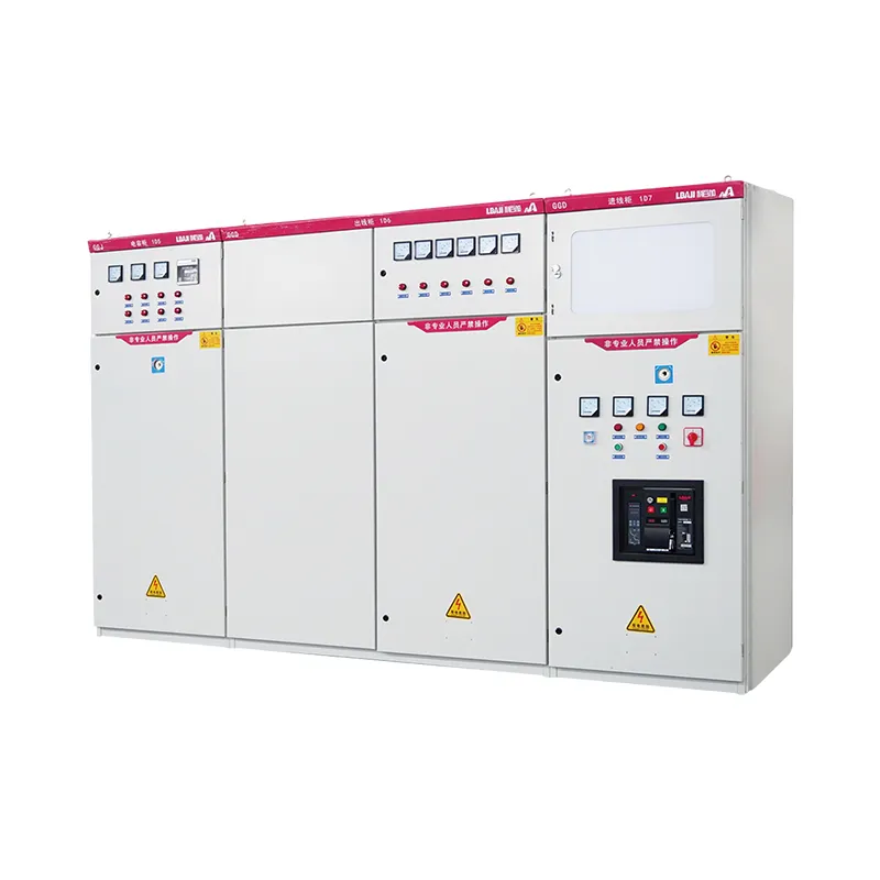
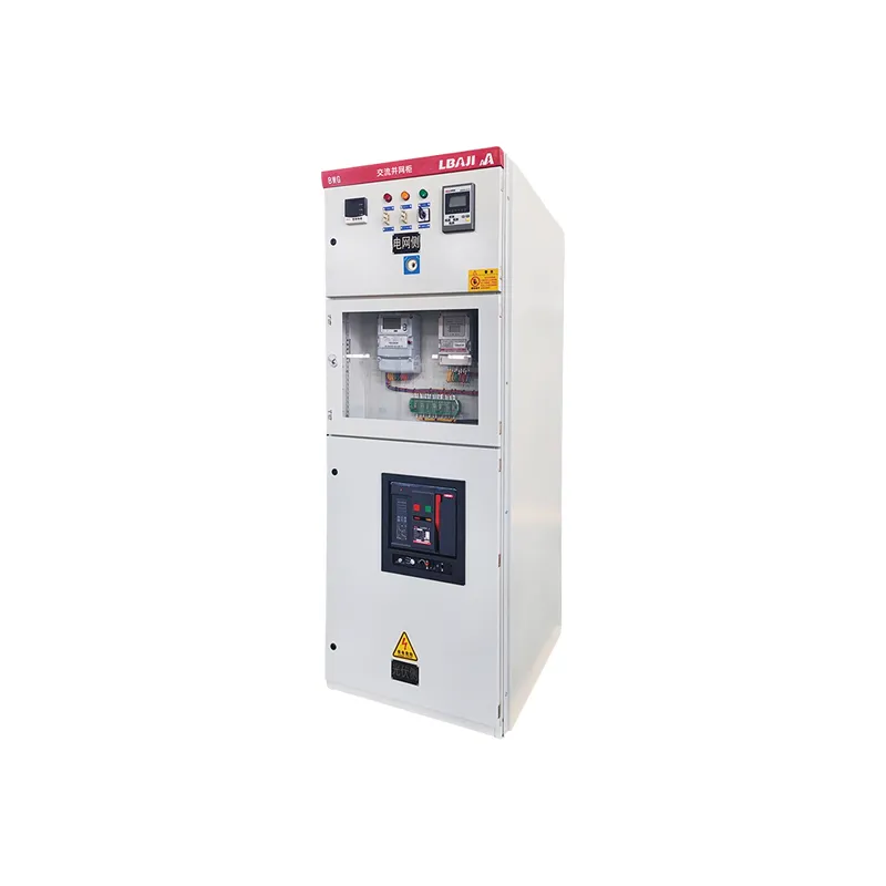
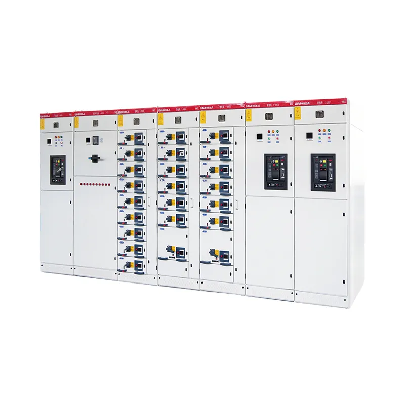
GGD low-voltage switchgear is an indoor, fixed-configuration AC distribution cabinet for low-voltage power distribution and control applications. This page describes the published installation conditions and the information required to specify a project cabinet. The final electrical ratings, circuit arrangement, protection devices and dimensions must be confirmed against the approved drawings and manufacturer data sheet.
Where a GGD Cabinet Fits
Published GGD series-level values
| Published parameter | Series-level information | Confirm for the offered cabinet |
|---|---|---|
| AC frequency | 50 Hz | Confirm compatibility with the project supply and exact equipment configuration. |
| Rated working voltage | 380 V | Confirm system voltage, insulation coordination and the voltage assigned to each circuit. |
| Rated working current | Up to 3,150 A across the published series description | Confirm the selected incomer, busbars, feeder ratings and temperature-rise verification for the specific lineup. |
These values do not establish short-circuit withstand, breaker interrupting capacity, protection settings, enclosure rating, circuit count or dimensions. Require the supplier to state those model- and project-specific values in the approved technical schedule.
Use a GGD assembly when the project calls for a low-voltage distribution cabinet with a defined incoming supply, outgoing circuits and protection arrangement. The selection depends on the actual one-line diagram, connected loads, available short-circuit current and service access. A model name alone cannot establish the busbar rating, fault withstand, enclosure degree or number of feeders. Those values belong in the project-specific technical schedule.
The existing product description states that this GGD series is designed and manufactured in accordance with IEC 61439 and the applicable GB/T 7251 requirements. Ask for the applicable design-verification and routine-verification documents for the offered configuration. Standard references do not substitute for reviewing the exact assembly and installation.
GGD Switchgear Specification Checklist
| Specification field | Information to provide or confirm | Why it matters |
|---|---|---|
| System and incoming supply | Nominal voltage, phase, frequency, earthing arrangement and incoming cable or busduct details | Determines component and connection requirements |
| Current and fault duty | Calculated load, required busbar current, available short-circuit current and protection study | Supports thermal and short-circuit verification |
| Outgoing circuits | Feeder count, ratings, protective-device types, metering and spare ways | Defines the actual panel arrangement |
| Installation | Indoor room conditions, cable-entry direction, access clearances and space available | Checks the cabinet against the physical site |
| Documentation | Single-line drawing, layout, component list, verification records and operation manual | Allows review before manufacture and acceptance |
Configuration and Acceptance
For a new build, submit the one-line diagram and load schedule before the cabinet arrangement is finalized. Identify which feeders are essential, which require metering and which may expand later. For a replacement, add photos of the existing nameplate, connection points and installation space. Confirm the direction of cable entry and the path needed to move the equipment into place.
Before acceptance, compare the delivered cabinet against the approved drawing and agreed component list. Request the applicable verification records, routine test results, wiring drawings and final nameplate information. Confirm labels, access, clearances and protection settings with the project engineer. Electrical work and commissioning must follow local rules and qualified-person procedures.
Request a Project-Specific GGD Quotation
For a structured inquiry, download the GGD project specification and RFQ worksheet (PDF). It collects the buyer’s requirements and supplier confirmations; it is not a certified product datasheet.
Send the rated system information, single-line diagram, feeder schedule, short-circuit study, installation conditions, quantity and delivery location through the contact page. If the design is still being compared, review our switchgear versus switchboard guide and electrical control panel guide to separate distribution and control requirements.
Service Conditions
- Ambient air temperature: −5 °C to +40 °C; the 24-hour average temperature shall not exceed +35 °C.
- Altitude: The installation site shall not exceed 2,000 m above sea level. The equipment is intended for indoor installation and operation.
- Relative humidity: The relative humidity shall not exceed 50% at a maximum ambient temperature of +40 °C. Higher relative humidity is permitted at lower temperatures, for example, up to 90% at +20 °C, taking into account the possibility of occasional condensation caused by temperature variations.
- Installation inclination: The equipment shall be installed with an inclination of no more than 5° from the vertical plane.
- Installation site: The equipment shall be installed in a location free from severe vibration, shock, and corrosive gases or vapors that may adversely affect electrical components.
- Any special requirements shall be agreed upon with the manufacturer.
Reviews
There are no reviews yet.