High voltage allows electric power to move long distances with lower current and lower conductor losses, but it also increases insulation, clearance, protection and safety requirements. This guide explains what voltage is considered high voltage, how AC transmission and high-voltage direct current (HVDC) differ, what equipment is used in substations, and which technical data matter when specifying a high-voltage project.
What Voltage Is Considered High Voltage?
There is no single universal boundary. Definitions vary by safety regulation, equipment standard and industry. IEC equipment terminology commonly places medium voltage above 1 kV and up to several tens of kilovolts, with high voltage above that range; utility planners may also use high voltage, extra-high voltage and ultra-high voltage bands. Occupational-safety rules can call much lower voltages “high voltage” for work-control purposes.
Therefore, a specification should state the nominal voltage and highest voltage for equipment rather than rely on the phrase “high voltage.” A 35 kV network, a 132 kV transmission line and a ±500 kV HVDC link require very different equipment.
Why Transmit Power at High Voltage?
Three-phase apparent power is approximately √3 × voltage × current. For the same transmitted power, increasing voltage reduces current. Resistive conductor loss equals current squared times resistance, so lower current greatly reduces loss and voltage drop and can reduce required conductor cross-section.
The tradeoff is higher cost for insulators, towers, clearances, bushings, transformers, switchgear and surge protection. Network design balances transmission distance, power level, right-of-way, losses, reliability and lifecycle cost.
Quick Comparison and Selection Table
Use this table as a quick review of the main engineering and procurement decisions explained in the article.
| Decision area | Practical meaning | What to verify |
|---|---|---|
| What Voltage Is Considered High Voltage? | There is no single universal boundary. | Definitions vary by safety regulation, equipment standard and industry. |
| Why Transmit Power at High Voltage? | Three-phase apparent power is approximately √3 × voltage × current. | For the same transmitted power, increasing voltage reduces current. |
| High-Voltage AC Transmission | Most interconnected grids use three-phase AC because transformers efficiently step voltage between generation, transmission and distribution levels. | A generating plant raises voltage for transmission; receiving substations reduce it through sub-transmission and distribution stages. |
| High-Voltage Direct Current Transmission | HVDC transmits power as direct current between converter stations. | It can be advantageous for very long overhead routes, long submarine or underground cables, controlled bulk transfer and interconnection of asynchronous AC systems. |
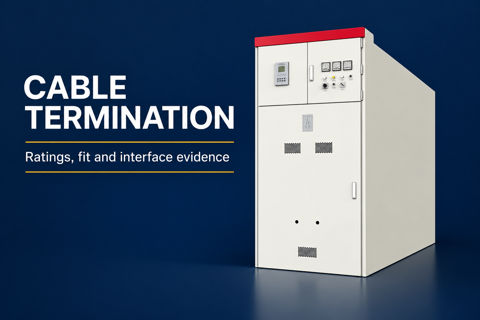
| Essential High-Voltage Equipment | LBAJI’s 35 kV oil-immersed power transformer supports sub-transmission and distribution projects. | At the switchgear level, KYN61-40.5 metal-clad switchgear provides a 40.5 kV-class platform for indoor systems. |
High-Voltage AC Transmission
Most interconnected grids use three-phase AC because transformers efficiently step voltage between generation, transmission and distribution levels. A generating plant raises voltage for transmission; receiving substations reduce it through sub-transmission and distribution stages.
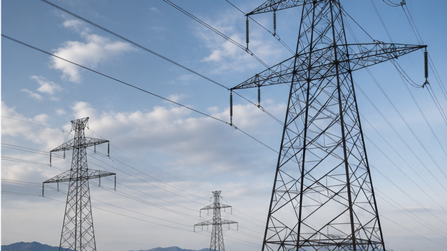
Overhead line design considers conductor thermal rating, sag, corona, electric and magnetic fields, lightning performance, insulation coordination, wind and ice loading, tower geometry and ground clearance. Underground cables avoid towers but have higher capacitance, thermal constraints and repair complexity.
High-Voltage Direct Current Transmission
HVDC transmits power as direct current between converter stations. It can be advantageous for very long overhead routes, long submarine or underground cables, controlled bulk transfer and interconnection of asynchronous AC systems. Converter losses and cost mean it is not automatically better for every project.
Line-commutated converter systems are established for very high bulk-power transfer and require strong AC systems and reactive-power support. Voltage-source converters offer flexible control and can serve weaker grids and offshore connections, but project economics and ratings determine the choice.
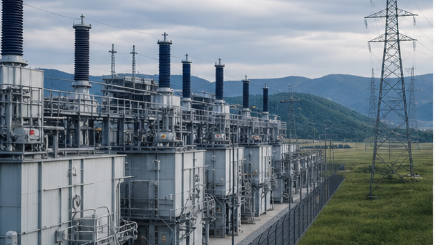
Essential High-Voltage Equipment
- Power transformers: change voltage and provide system connection and isolation.
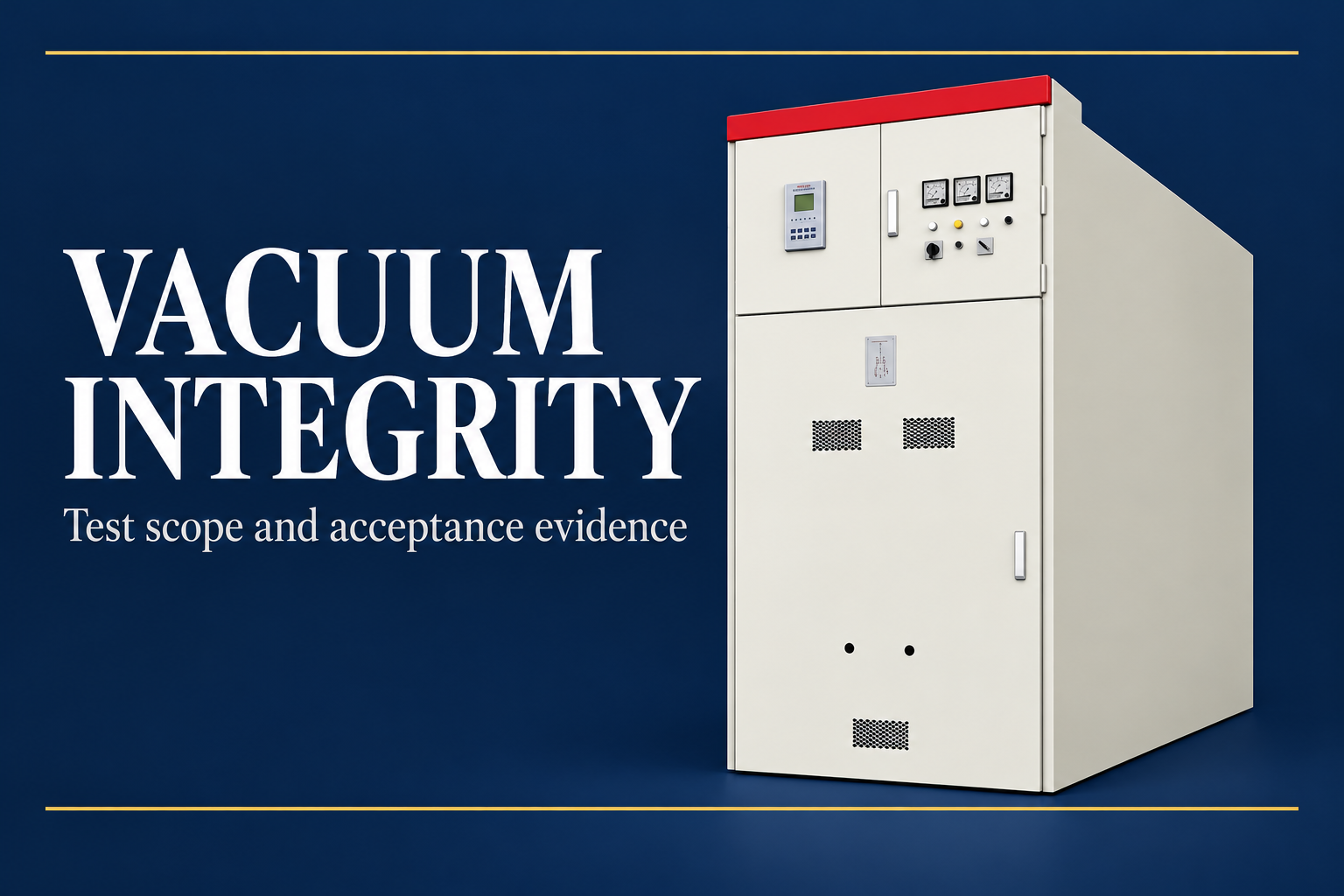
- Circuit breakers: interrupt load and fault current at the rated voltage.
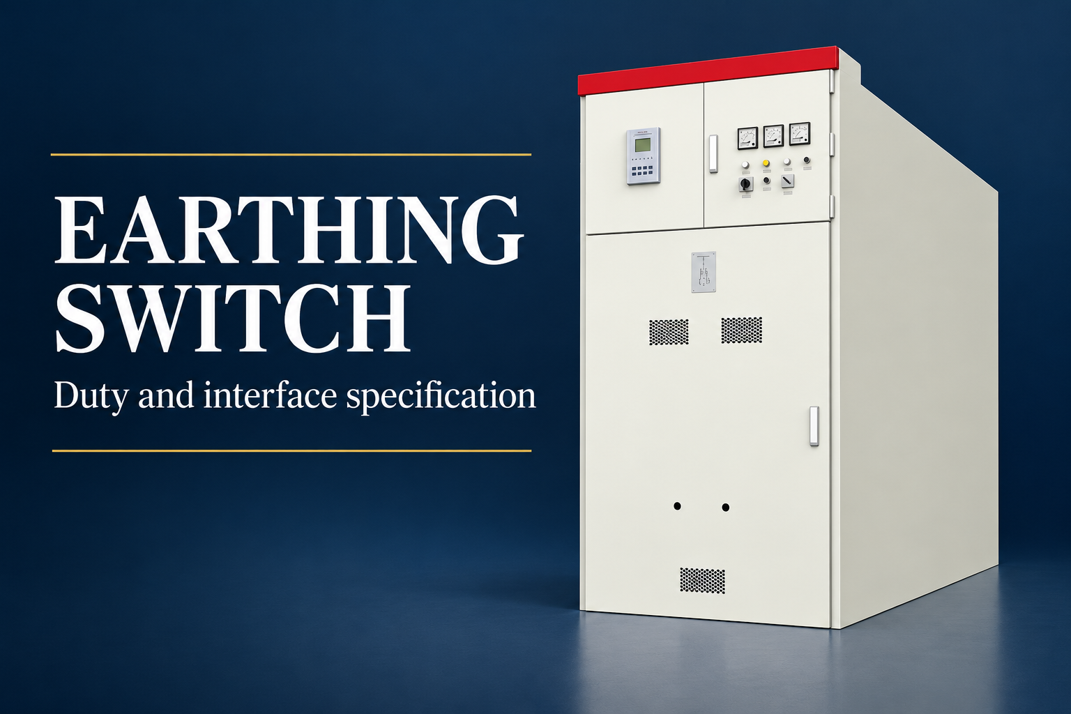
- Disconnectors and earthing switches: provide visible isolation and grounding after current interruption.
- Current and voltage transformers: scale primary quantities for meters and relays.
- Surge arresters: limit lightning and switching overvoltages.
- Busbars and conductors: interconnect bays and carry continuous and fault current.
- Protection and control: detect faults, trip the correct breakers and communicate system state.
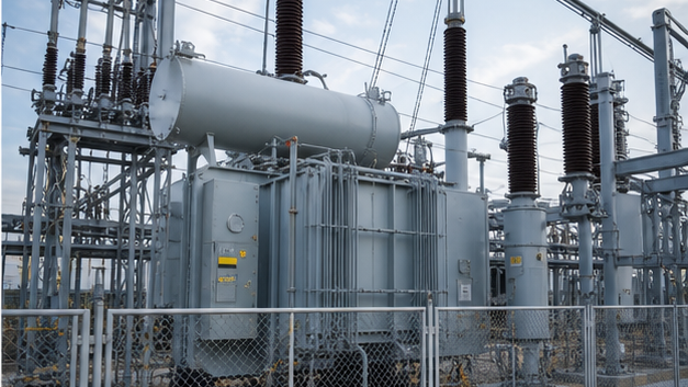
LBAJI’s 35 kV oil-immersed power transformer supports sub-transmission and distribution projects. At the switchgear level, KYN61-40.5 metal-clad switchgear provides a 40.5 kV-class platform for indoor systems.
Insulation Coordination
Insulation coordination matches equipment withstand levels to expected power-frequency, lightning and switching overvoltages. Engineers select clearances, creepage distance, bushings, surge arresters and shielding from system voltage, grounding, altitude, pollution and surge studies. Equipment impulse rating cannot be chosen independently from arrester protective level and physical layout.
Air density falls with altitude and can reduce external insulation strength and cooling. Coastal salt, industrial pollution, dust and condensation increase surface leakage risk. Project environmental data must therefore accompany voltage and current ratings.
High-Voltage Substation Arrangements
A substation may use a single bus, sectionalized bus, double bus, ring bus or breaker-and-a-half arrangement. More complex schemes improve operational flexibility and fault isolation but require more equipment and protection logic. Air-insulated substations need more land; gas-insulated substations reduce footprint and environmental exposure but use sealed modules and specialized service practices.
At distribution level, a 35 kV new-energy box-type substation integrates transformation and switching for renewable projects. A YBM-12 prefabricated substation offers a compact approach for 12 kV-class distribution.
Protection of High-Voltage Systems
Protection must clear faults quickly and selectively while remaining secure during load, inrush, power swings and external faults. Typical schemes include line distance or differential protection, transformer differential and restricted earth fault, busbar differential, breaker failure and overcurrent backup. Redundant relays, DC supplies and trip coils may be required for critical transmission assets.
Fault clearing time affects equipment damage, stability and arc energy. Settings must be derived from short-circuit and coordination studies and verified through commissioning tests that include the full CT-to-relay-to-breaker chain.
Living or Building Near High-Voltage Lines
Permitted setbacks, building heights, road crossings and work clearances are controlled by local utilities and authorities. A public map is not sufficient to establish legal easements or safe construction distance. Developers should obtain surveyed line data and written requirements from the line owner before design or excavation.
For public exposure questions, use guidance from the responsible health and regulatory authorities. Never enter a transmission right-of-way or approach conductors to make measurements without authorization.
High-Voltage Project Specification Checklist
- Nominal voltage, highest equipment voltage and frequency.
- System grounding and neutral treatment.
- Continuous current, power flow and future expansion.
- Maximum and minimum fault current and clearing time.
- Power-frequency and impulse insulation levels.
- Single-line diagram, bus arrangement and operating philosophy.
- Protection, control, metering and communications requirements.
- Altitude, temperature, pollution, seismic and corrosion conditions.
- Applicable standards, type tests, factory tests and site tests.
High-voltage classifications depend on the standard
The boundary between low, medium and high voltage is not universal. IEC equipment classes, IEEE practice, utility terminology and workplace rules may use different thresholds. Specifications should therefore state nominal and maximum system voltage, insulation level, frequency and grounding method rather than relying on the words “high voltage” alone.
Insulation coordination and high-voltage safety
Clearance, creepage, impulse withstand and surge-arrester protection must be coordinated with altitude, pollution and switching duty. Safe work also requires verified isolation, discharge, earthing, approach boundaries and controlled access. A circuit that is switched off is not proven safe until absence of voltage is tested and stored or induced energy is addressed.
Technical references and further reading
The following independent sources support the standards, terminology, calculations, and safety context discussed in this guide:
- NIST SI units for electric current — Authoritative definitions and relationships for amperes, volts, watts, and ohms.
- NIST Guide to SI electrical conversion factors — Official conversion factors for electricity, magnetism, energy, and related quantities.
- OSHA electrical safety requirements — Safety context for applying electrical calculations to transmission and distribution work.