A switchgear insulation resistance test measures the resistance of a defined insulation path under an approved direct-voltage test condition. Its value depends on the exact boundary, connected equipment, test voltage, elapsed time and environmental conditions. The useful result is a traceable assessment of that defined circuit, compared with the applicable instructions and suitable previous records. It is not a universal certificate that an assembly is safe to energize. This guide helps owners and procurement teams review a test plan and report; qualified personnel must establish and perform the actual work.
Know what the test can and cannot show
Insulation resistance can help identify conditions such as moisture, surface contamination or a change in an insulation path. A result may justify further investigation when compared with a trustworthy baseline. However, different defects respond differently to electrical tests. High resistance does not establish the absence of every mechanical defect, prove correct assembly, or replace all required dielectric and functional verification.
Keep insulation resistance distinct from contact resistance, protective-conductor continuity and withstand testing. Those methods address different questions and use different equipment or conditions. A maintenance report that lists only a large resistance number leaves important acceptance questions unanswered. The overall inspection and test plan should connect each method to the equipment condition or failure mode it is intended to investigate.
Define the equipment and circuit boundary
Identify the assembly, panel, bus section and insulation paths in the approved plan. State which equipment is included and which is disconnected, isolated or otherwise excluded under the manufacturer’s instructions. A reading across a switchgear assembly with attached cables is not directly comparable with a reading of the bare assembly. The additional equipment changes the object being measured.
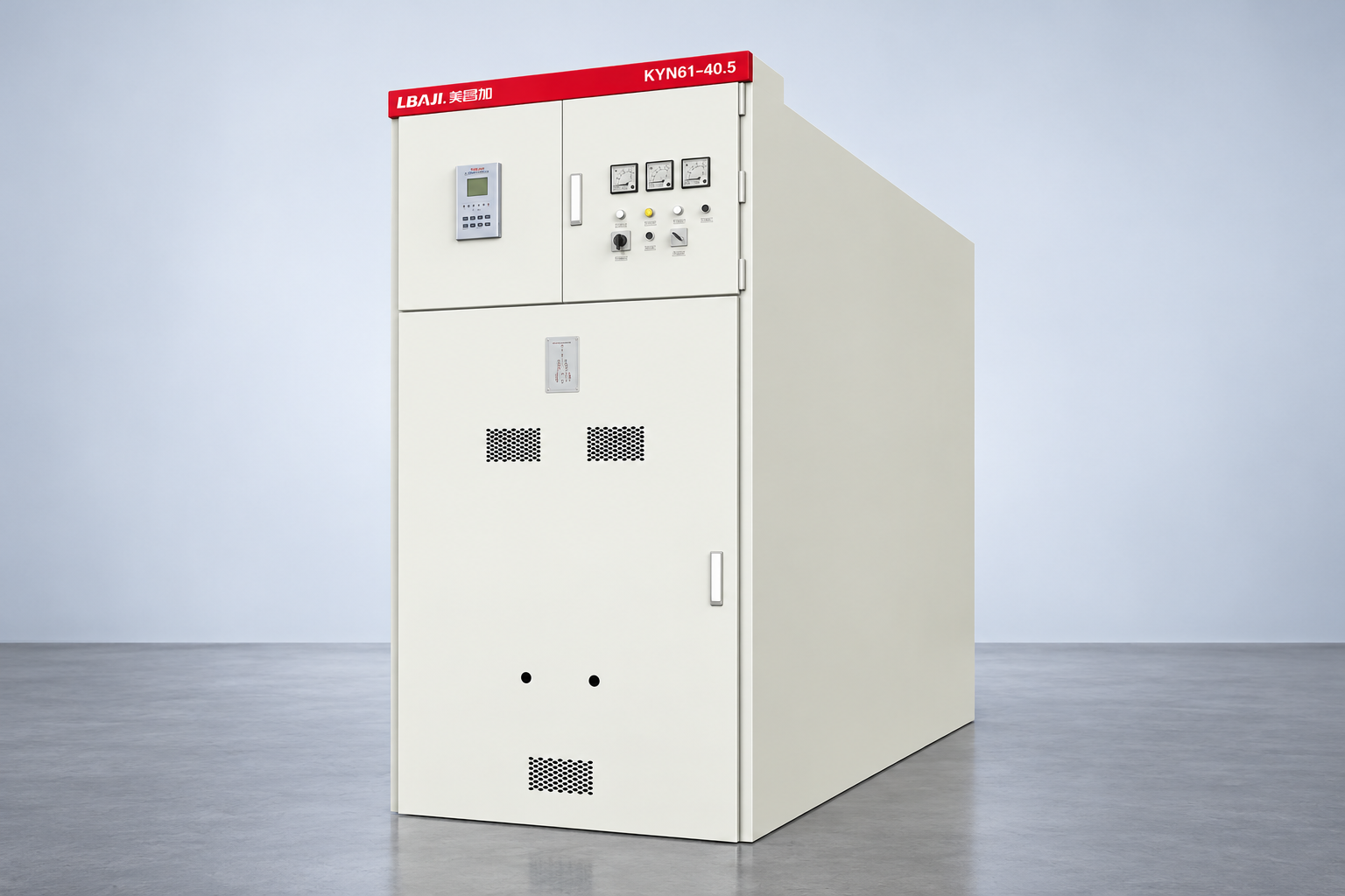
Prepare a boundary drawing or annotated schematic that a reviewer can understand without attending the test. Include the relevant switching states and excluded interfaces in the controlled work documentation. Do not guess internal connections from an exterior photograph. The LBAJI KYN61 images on this page identify the assembly family being discussed; they do not show a test setup, internal insulation path or approved connection sequence.

Make safe work prerequisites explicit
Electrical testing can introduce a hazardous voltage even when the normal supply has been isolated. The work method must address all sources, verification of the required safe condition, control of the test area, suitable equipment and the treatment of stored charge. Only authorized qualified personnel should perform it. This article does not provide a live-work method or terminal-by-terminal connection instructions.
The official work-practices reference below establishes the wider importance of safe electrical work. Project procedures must also address the actual assembly, nearby equipment and local legal requirements. Do not interpret a completed checklist in a commercial article as permission to proceed. A safe test needs a responsible person, an approved method and control of the real work boundary.
Protect connected components before applying a test
Modern switchgear can contain electronic relays, meters, surge-protective components, instrument transformers and other devices whose instructions affect the permissible test arrangement. A test voltage suitable for one insulation path may be unsuitable for a connected component. Obtain the manufacturer’s requirements and identify all affected interfaces before approving the plan.
Record exclusions and reconnection responsibilities. Disconnection can change both the test boundary and the functions available afterward. A test report should therefore be linked to the restoration checklist and final functional verification. The work is incomplete if the insulation result is accepted but a measuring circuit, protective function or intended earth connection has not been correctly restored and documented.
Choose voltage and timing from an approved basis
There is no single voltage and resistance limit that can safely be applied to every switchgear design. Use the equipment instructions, contract requirements and applicable test standard to establish the method. Distinguish factory verification, site commissioning and maintenance assessment. A value copied from an unrelated assembly or a general web table is not an adequate acceptance basis.
Timing matters because the indicated resistance can change during application of a DC test voltage. Record the specified duration and the time associated with each reading. If time-dependent measurements are required, use the approved interpretation method for that equipment. Do not assume that a ratio developed for another insulation system is automatically meaningful for a complete mixed-component assembly.
Build a report that supports a decision
Reference context: University of Hong Kong: Testing Conductors and Protective Devices, laboratory teaching reference. This original qualitative checklist organizes project decisions; it is not a reproduced standard or a substitute for approved criteria.
| Report field | Information to retain | Why it matters |
|---|---|---|
| Equipment identity | Assembly, panel and circuit references | Prevents a result being assigned to the wrong asset |
| Test boundary | Included paths, connected equipment and exclusions | Makes comparisons electrically meaningful |
| Method | Approved voltage, timing and acceptance basis | Shows how the result should be interpreted |
| Conditions | Relevant temperatures, humidity and observed surface condition | Helps explain changes unrelated to permanent damage |
| Instrument | Identification, range and applicable calibration information | Supports confidence in the recorded measurement |
| Outcome | Readings, abnormalities, actions and responsible approval | Converts a number into a controlled decision |
A report can use a digital form, but it should preserve original observations and revision history. Where the instrument reports an over-range indication, record that indication accurately. Do not convert it into a precise resistance value that the instrument did not measure. Missing environmental data or an undocumented boundary should remain a limitation rather than being reconstructed from memory after the event.
Interpret temperature, moisture and surface condition
Resistance readings are affected by insulation temperature and surface conditions. Where comparison requires temperature correction, use a supported correction method applicable to the insulation system. An arbitrary correction factor can produce a neat chart with a misleading engineering conclusion. Record measured or justified temperature information and clearly distinguish it from ambient air temperature when those are different.
Moisture, dust or contamination can create surface leakage paths. Review inspection findings alongside the electrical data. If cleaning or drying is authorized, document the method, the equipment condition before and after treatment and the resulting repeat test. A higher result after maintenance may be useful evidence, but it does not automatically resolve every underlying cause or establish readiness for service.
Compare like with like
For trend analysis, confirm that the equipment boundary, test voltage, duration, connected devices and relevant conditions are sufficiently comparable. An apparent improvement can come from disconnecting a cable or removing a component rather than improving insulation condition. Similarly, a lower result can reflect a changed setup. State these differences explicitly before drawing a degradation conclusion.
Comparisons between phases or sections can identify a reason to investigate, but they are not a substitute for the applicable limits and configuration review. An asymmetry should prompt an examination of the actual circuit, conditions and repeatability. Avoid declaring a specific fault from one number alone. Keep the interpretation proportional to the evidence and refer unresolved findings to the responsible engineering authority.

Investigate an unexpected result systematically
First establish whether the test was valid: correct asset, approved boundary, suitable instrument, correct method and complete conditions. Then review relevant inspection observations, previous records and component instructions. This sequence helps separate a setup problem from a possible equipment issue. Any repeat measurement must remain within the approved method and safe work controls.
Where a genuine abnormality remains, define the next investigation and acceptance hold point. Additional testing or manufacturer consultation may be required. Do not keep increasing the voltage, changing the boundary or repeating tests until a preferred result appears. The objective is a trustworthy assessment, with uncertainty recorded and a defensible decision on further action.
Keep acceptance separate from energization authorization
An acceptable insulation-resistance result is one item in the commissioning or maintenance evidence package. Other required inspections, protection tests, mechanical checks, connection verification and defect closures still apply. A person approving the electrical test report may not be the person authorized to release the installation for energization. Make those responsibilities explicit in the plan.
After testing, complete the approved discharge, restoration and verification process before the work boundary is released. Record the status of temporary connections, disconnected devices, covers and protection interfaces. The sequence must come from the actual equipment and site procedures. A general article cannot prescribe how long a particular assembly must be discharged or which terminals may be handled.
Specify testing evidence in a purchase order
For new equipment, ask the supplier to identify the supplied test documentation, governing requirements and site instructions. Clarify whether any site test is required, who performs it and how the assembly must be prepared. Keep factory and site responsibilities separate. This prevents a delivery certificate being mistaken for proof that installation work and site interfaces have been accepted.
For existing equipment, provide the available asset records, previous results, observed conditions and planned outage boundary. Ask the service provider to state the method, exclusions, instrument requirements and deliverables before work begins. The quotation should include how abnormal findings will be handled, rather than promising a pass without knowing the equipment condition.
Use the result as part of an equipment history
Retain the approved report with the as-built drawings and maintenance history. Record any cleaning, drying, component replacement or boundary change that affects future interpretation. Make the next reviewer able to reconstruct what was actually measured. A spreadsheet containing only dates and resistance values loses the context needed for a reliable condition assessment.
The University of Hong Kong laboratory reference linked below distinguishes insulation testing from conductor continuity and protective-device testing. Its teaching setup is useful background, not a universal acceptance schedule or method for a medium-voltage switchgear assembly. Apply the current equipment instructions and project requirements, and have the responsible engineer resolve conflicts before testing or acceptance.
Frequently asked questions
Is one resistance value enough to accept switchgear?
No. Interpret the result against the approved method, equipment boundary, conditions and acceptance basis, together with the other required inspection and test records.
What test voltage should be used?
Use the manufacturer’s instructions and applicable project requirements for the defined insulation path. There is no universal value suitable for all assemblies and connected components.
Can connected relays and surge devices remain in circuit?
Only where the approved method and their instructions allow it. Identify affected components and document exclusions, restoration and final verification before work begins.
Why do readings change between inspections?
Temperature, moisture, surface condition, test timing and equipment boundaries can change the result. Compare the setup and conditions before concluding that insulation has deteriorated.
Does an over-range indication mean infinite resistance?
No. It means the result exceeds the instrument’s indicated measuring range under the stated conditions. Record the actual indication and instrument capability without inventing a precise value.
Technical sources and related equipment
Standard catalogue pages establish document scope; compliance and acceptance require the applicable full documents and project engineering review.
- University of Hong Kong: Testing Conductors and Protective Devices, laboratory teaching reference
- UK HSE HSG85: Electricity at work, safe working practices
- LBAJI KYN61-40.5 Armouring Removable AC Metal Enclosed Switchgear
- switchgear equipment fundamentals
- switchgear verification and testing
- current-transformer fundamentals
Further learning: technical background
This independent educational video explains the measurement principles or equipment background discussed above. It does not demonstrate a safe work procedure for the specific assembly. Source: NPTEL IIT Guwahati.