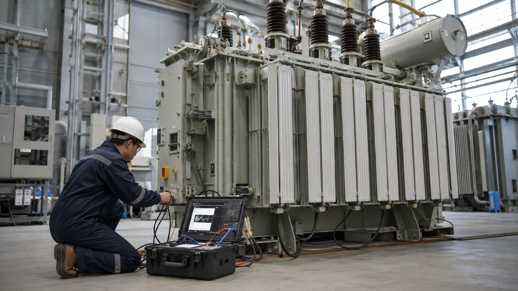
A transformer calculator converts load power, voltage, phase, power factor, and efficiency into the kVA and current needed for initial selection. The result is a starting point. A reliable specification must also consider demand and diversity, motor starting, harmonics, ambient temperature, altitude, impedance, fault duty, voltage regulation, future growth, and the manufacturer’s standard ratings.
Core transformer kVA formulas
Single-phase transformer calculator
For a single-phase circuit, kVA = V × I ÷ 1,000. Rearranged, full-load current is I = kVA × 1,000 ÷ V. A 75 kVA, 240 V secondary therefore has a calculated full-load current of 312.5 A.
Three-phase transformer calculator
For a balanced three-phase circuit, kVA = √3 × VLL × I ÷ 1,000. Current is I = kVA × 1,000 ÷ (√3 × VLL). A 1,000 kVA transformer at 400 V has a secondary full-load current of about 1,443 A.
If load information is given in kW, estimate kVA = kW ÷ (power factor × efficiency). Do not add kW and kVA values directly. Convert every load to a common basis before applying demand and diversity assumptions.

Step-by-step transformer sizing method
- List each load with voltage, phase, kW or kVA, power factor, efficiency, starting method, duty cycle, and harmonic characteristics.
- Convert loads to kVA and apply defensible demand and diversity factors.
- Check the largest motor or cyclic load separately for starting voltage drop and thermal duty.
- Add documented expansion capacity without creating excessive permanent oversizing.
- Select the next suitable standard transformer rating and verify it with the manufacturer.
For critical facilities, evaluate contingency operation and redundancy. Two transformers sharing normal demand may each need enough capacity for essential loads after one unit is removed, depending on the required service level.
Quick Comparison and Selection Table
Use this table as a quick review of the main engineering and procurement decisions explained in the article.
| Decision area | Practical meaning | What to verify |
|---|---|---|
| Core transformer kVA formulas | For a single-phase circuit, kVA = V × I ÷ 1,000 . | Rearranged, full-load current is I = kVA × 1,000 ÷ V . |
| Step-by-step transformer sizing method | For critical facilities, evaluate contingency operation and redundancy. | Two transformers sharing normal demand may each need enough capacity for essential loads after one unit is removed, depending on the required service level. |
| Primary and secondary current example | Consider a 500 kVA, three-phase transformer rated 10 kV/400 V. | Primary current is approximately 28.9 A: 500,000 ÷ (√3 × 10,000). |
| Transformer impedance calculator concepts | Percent impedance is the percentage of rated voltage needed to circulate rated current with the secondary shorted under test conditions. | A rough symmetrical terminal fault-current estimate is I sc ≈ I FL × 100 ÷ Z% , assuming a strong source. |
| Fuse, breaker, and wire sizing | A transformer primary fuse size calculator cannot be reduced to one universal multiplier. | Protection must allow magnetizing inrush and normal overload while clearing damaging faults within the transformer withstand curve. |
Primary and secondary current example
Consider a 500 kVA, three-phase transformer rated 10 kV/400 V. Primary current is approximately 28.9 A: 500,000 ÷ (√3 × 10,000). Secondary current is approximately 721.7 A: 500,000 ÷ (√3 × 400). Actual measured values depend on load, voltage, losses, imbalance, and harmonics.
This current calculation helps compare products such as an SCB10 dry-type transformer with the connected switchgear and cables, but it does not replace a complete coordination study.
Transformer impedance calculator concepts
Percent impedance is the percentage of rated voltage needed to circulate rated current with the secondary shorted under test conditions. A rough symmetrical terminal fault-current estimate is Isc ≈ IFL × 100 ÷ Z%, assuming a strong source. With 6% impedance, the idealized current is about 16.7 times full-load current.
The real system result also includes utility source impedance, upstream transformer impedance, cables, busbars, motors, and X/R ratio. Use a proper short-circuit study for equipment interrupting and withstand ratings.

Fuse, breaker, and wire sizing
A transformer primary fuse size calculator cannot be reduced to one universal multiplier. Protection must allow magnetizing inrush and normal overload while clearing damaging faults within the transformer withstand curve. Local electrical codes, voltage, transformer type, impedance, upstream coordination, secondary protection, and manufacturer recommendations determine permissible settings.
Similarly, wire size depends on ampacity, installation method, ambient temperature, grouping, insulation rating, voltage drop, short-circuit thermal withstand, termination rating, and applicable rules. Coordinate the secondary conductors and main breaker with the selected low-voltage switchgear.

Buck and boost transformer calculation
For buck-boost applications, first calculate the required voltage change and load current. The transformed kVA is approximately the voltage correction multiplied by load current, divided by 1,000 for single phase. Because an autotransformer connection transfers much of the power conductively, its unit kVA may be smaller than the load kVA. Use the manufacturer’s connection table for the exact source, target voltage, phase, and unit.
Information needed for final selection
Give the supplier primary and secondary voltage, phase, frequency, continuous and peak kVA, load type, harmonic spectrum, vector group, taps, impedance, insulation level, enclosure, cooling, ambient temperature, altitude, noise target, efficiency requirement, accessories, and required standards. A transparent load schedule makes the calculation auditable and prevents false precision.
Formulas used in a transformer calculator
Single phase: kVA = V × I ÷ 1,000. Three phase: kVA = 1.732 × V × I ÷ 1,000. Rearranging gives current. When starting from useful kW, divide by power factor and efficiency as applicable before selecting transformer kVA.
How to interpret calculator results
The calculated value is an electrical starting point, not an automatic product selection. Check load diversity, motor starting, harmonics, ambient temperature, impedance, voltage regulation and growth. Calculate both winding currents, then coordinate cables and protective devices using the governing installation rules and manufacturer data.
Technical references and further reading
The following independent sources support the standards, terminology, calculations, and safety context discussed in this guide:
- IEC 60076-1 power transformer standard — Scope, terminology, ratings, connection symbols, testing, safety, and general requirements for power transformers.
- U.S. Department of Energy: Distribution Transformers — Official definitions, efficiency requirements, test procedures, and regulatory resources for distribution transformers.
- OSHA electric power transmission and distribution requirements — Safety requirements relevant to construction and work around electric power transmission and distribution equipment.