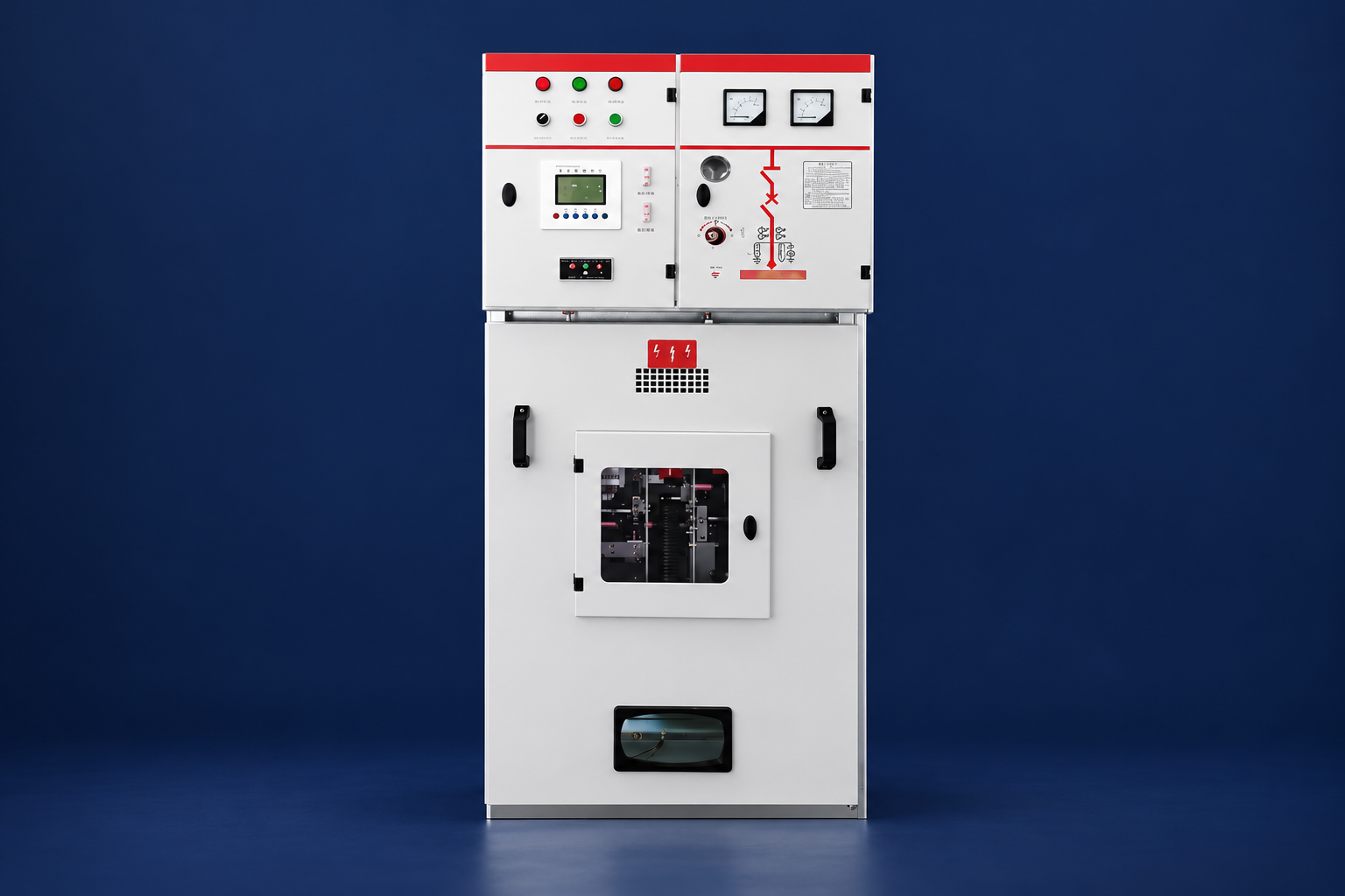
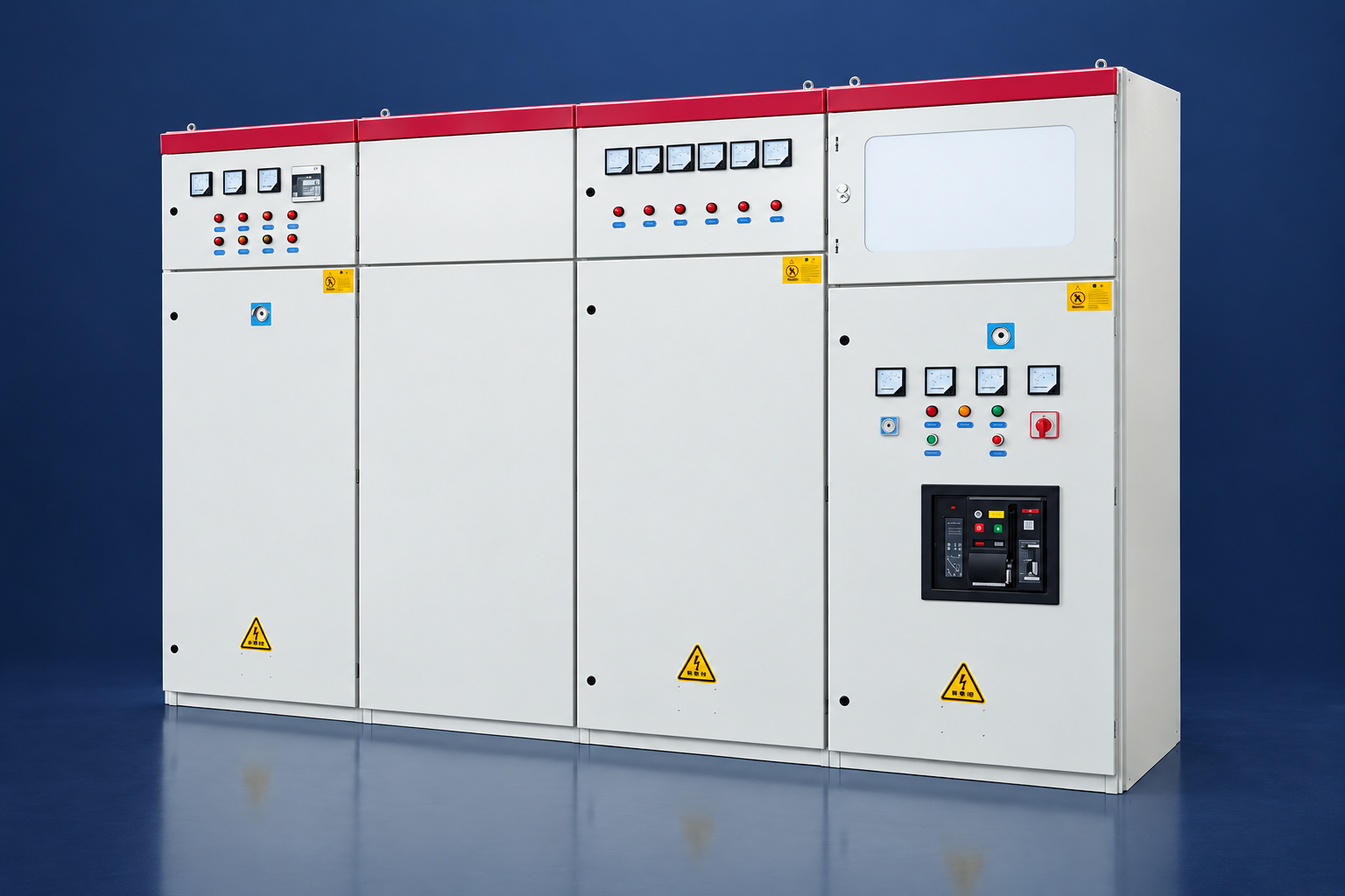
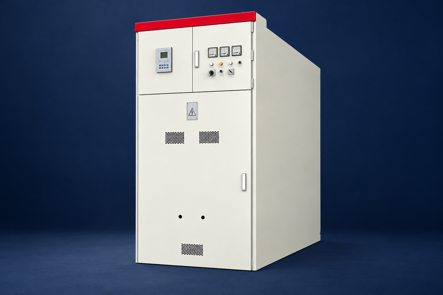
Low-voltage switchgear receives power from transformers, generators or utility services and distributes it through main, tie and feeder devices. Compared with a simple panelboard, LV switchgear is engineered for higher current, fault duty, compartmentation, maintainability and control. This guide covers ACB/MCCB selection, busbars, short-circuit ratings, fixed and withdrawable construction, separation, protection, arc safety and testing.
What Is Low-Voltage Electrical Switchgear?
LV switchgear is a factory-built assembly containing switching and protective devices, busbars, control circuits, metering and enclosures for systems up to the applicable low-voltage limit. Typical services include 400/230 V, 415/240 V, 480/277 V and 690 V AC.
A lineup may include incoming mains, bus coupler, generator incomer, automatic transfer, outgoing feeders, motor starters, capacitor banks and metering. The complete assembly needs verified temperature-rise and short-circuit performance.
Main Components
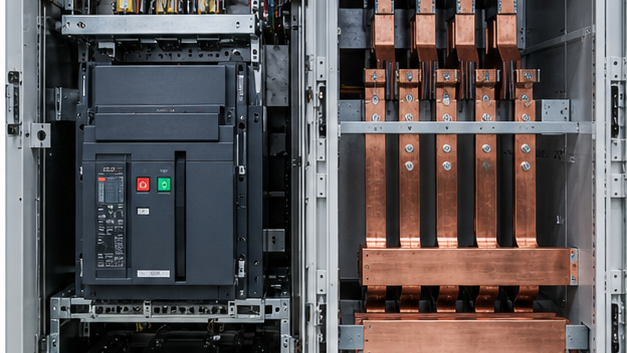
- Air circuit breakers: main and tie positions with adjustable electronic protection and high current ratings.
- Molded-case circuit breakers: feeders and smaller incomers with thermal-magnetic or electronic trips.
- Busbars: phase, neutral and protective-earth conductors with supports and joints.
- CTs and meters: current/voltage measurement, power quality and energy data.
- Control system: transfer, interlocking, remote I/O, communications and alarms.
- Enclosure: compartments, barriers, doors, cable spaces and arc-pressure paths.
Quick Comparison and Selection Table
Use this table as a quick review of the main engineering and procurement decisions explained in the article.
| Decision area | Practical meaning | What to verify |
|---|---|---|
| What Is Low-Voltage Electrical Switchgear? | LV switchgear is a factory-built assembly containing switching and protective devices, busbars, control circuits, metering and enclosures for systems up to the applicable low-voltage limit. | Typical services include 400/230 V, 415/240 V, 480/277 V and 690 V AC. |
| ACB vs MCCB | An ACB is commonly used for high-current main and tie service and may be drawout. | It offers adjustable long-time, short-time, instantaneous and earth-fault functions. |
| Fixed vs Withdrawable Construction | Fixed devices are bolted into position and can reduce cost and complexity. | Withdrawable units provide connected, test and isolated positions and can reduce replacement time. |
| Essential Ratings | Specify rated voltage, insulation voltage, impulse withstand, frequency, busbar current, neutral rating, short-time withstand current and duration, peak withstand, breaker breaking capacity, enclosure IP/NEMA and… | Assembly ratings and device ratings are not interchangeable. |
| Busbar Design | Copper or aluminum busbars must satisfy continuous temperature rise and short-circuit thermal/electrodynamic forces. | Joint preparation, plating, bolt control, supports, ventilation and proximity effects matter. |
ACB vs MCCB
An ACB is commonly used for high-current main and tie service and may be drawout. It offers adjustable long-time, short-time, instantaneous and earth-fault functions. An MCCB is compact and serves feeders and smaller mains. Both must be selected for voltage, continuous current, breaking capacity, utilization category and coordination—not frame size alone.
Fixed vs Withdrawable Construction
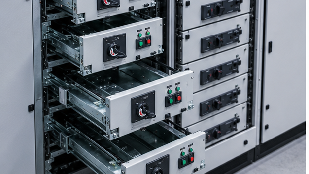
Fixed devices are bolted into position and can reduce cost and complexity. Withdrawable units provide connected, test and isolated positions and can reduce replacement time. They require shutters, position indication and interlocks. The project should justify withdrawability from availability and maintenance needs rather than specify it automatically.
Essential Ratings
Specify rated voltage, insulation voltage, impulse withstand, frequency, busbar current, neutral rating, short-time withstand current and duration, peak withstand, breaker breaking capacity, enclosure IP/NEMA and ambient conditions. Assembly ratings and device ratings are not interchangeable.
Busbar Design
Copper or aluminum busbars must satisfy continuous temperature rise and short-circuit thermal/electrodynamic forces. Joint preparation, plating, bolt control, supports, ventilation and proximity effects matter. Nonlinear loads may require a full or oversized neutral because triplen harmonics add in the neutral.
Forms of Separation
Internal separation divides busbars, functional units and terminals with barriers or partitions. Higher forms can reduce accidental contact and support maintenance but add space and cost. Specify the actual access and continuity objective; a form number alone does not authorize work on energized adjacent sections.
Protection Coordination
Protection settings should clear the closest device first while protecting cables, transformer and busbars. Review time-current curves, instantaneous thresholds, current-limiting effects, transformer inrush, motor starting and arc-flash clearing time. Zone-selective interlocking can permit fast bus-fault clearing while maintaining feeder selectivity.
Arc Safety
Arc faults can release intense heat and pressure. Mitigation includes robust assembly, compartmentation, insulated busbars, maintenance, arc-detection relays, fast clearing, remote operation and arc-resistant construction. An arc-tested assembly must be installed with the tested vent path and room conditions. Safe work procedures remain essential.
Automatic Transfer and Paralleling
Main-tie-main schemes transfer loads between two transformers. Generator switchgear may synchronize sources and share load. Control must prevent unintended paralleling, verify source health, manage transition timing and shed load when source capacity is limited. Mechanical and electrical interlocks should match the operating philosophy.
Integration With LBAJI Equipment
LV switchgear often forms the secondary distribution section of a YBM-12 prefabricated substation or 35 kV new-energy box substation. Upstream MV protection can use KYN28A-12 switchgear. Transformer impedance and the operating configuration determine LV fault duty.
Factory Acceptance Testing
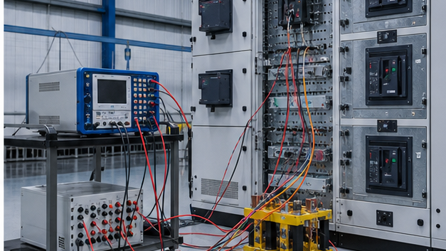
FAT includes visual and dimensional checks, wiring continuity, dielectric and protective-circuit tests, mechanical operation, breaker settings, interlocks, metering, communications, transfer logic and alarm simulation. Type-test or design-verification evidence should cover the offered construction and ratings.
Specification Checklist
- Single-line, voltage, frequency and grounding.
- Normal/emergency load and busbar current.
- Maximum/minimum fault current and duration.
- Main, tie and feeder protection functions.
- Fixed/withdrawable construction and separation.
- Neutral, earth, SPD and metering.
- Transfer, generator and communication logic.
- Environment, enclosure, cable entry and access.
- Standards, verification, FAT and commissioning.
How LV switchgear protection devices work together
ACBs and MCCBs interrupt faults, fuses provide fast current limitation, relays or electronic trip units decide when to operate, and disconnect switches establish isolation. Their time-current behavior must coordinate so a branch fault does not unnecessarily trip the main incomer.
LV switchgear installation and maintenance
Verify room temperature, ventilation, cable support, gland plates, bonding, torque and working clearances during installation. Maintenance should include visual inspection, cleaning where appropriate, mechanical operation, contact and insulation checks, protection testing and examination of abnormal temperature or fault records.
Technical references and further reading
The following independent sources support the standards, terminology, calculations, and safety context discussed in this guide:
- IEC 62271-200 metal-enclosed switchgear standard — Scope, classifications, service conditions, internal-arc testing, interlocks, and requirements for AC metal-enclosed switchgear up to 52 kV.
- IEEE C37.121 guide for switchgear-unit substations — Coordination guidance for switchgear and transformer sections in three-phase unit substations.
- OSHA electrical power safety requirements — Safety requirements for construction involving electric power transmission and distribution equipment.