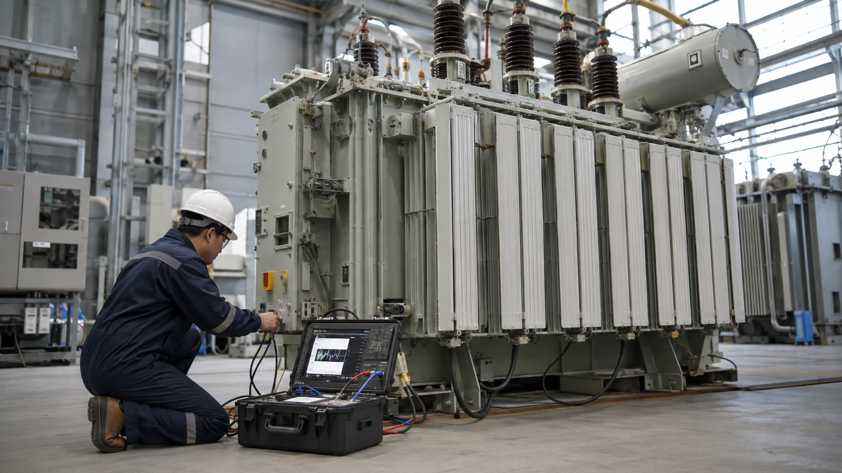
Transformer parts work as one thermal, dielectric, magnetic and mechanical system: the core and windings transfer energy, insulation controls electric stress, the tank and cooling circuit remove heat, bushings connect conductors, and protection accessories detect abnormal conditions. A parts list is useful only when it is tied to transformer type, rating, serial data, drawings and the failure being corrected. This guide explains functions, inspection evidence and RFQ information without assuming that parts from similar-looking units are interchangeable.
Key Takeaways
- Use the nameplate, outline drawing and accessory schedule to identify parts.
- Treat bushings, gaskets, oil, tap changers and protection devices as engineered interfaces.
- Confirm dimensions, ratings, materials and tests before accepting a substitute.
Magnetic Core and Windings
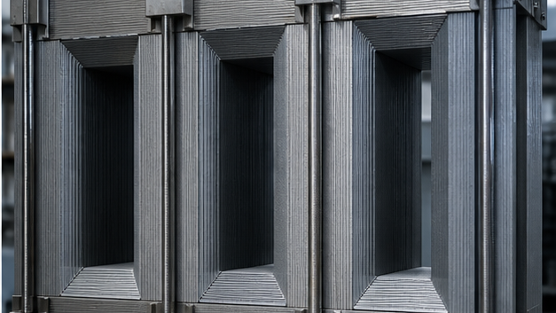
The laminated electrical-steel core carries alternating flux while limiting eddy-current loss. Step-lap joints, clamping pressure and grounding influence noise and circulating current. Windings use copper or aluminum conductors arranged to withstand operating voltage, short-circuit force and temperature. Axial spacers, radial ducts and pressboard cylinders provide cooling paths and mechanical restraint.
A winding cannot be specified by resistance alone. Turns, conductor area, insulation build, transposition, tapping arrangement and dimensional fit determine ratio, impedance and thermal behavior. Core or winding replacement is normally a factory-level engineering task supported by design calculations and post-repair routine tests.
Tank, Oil Preservation and Cooling Parts
The tank supports the active part, contains insulating liquid and transfers internal pressure and transport loads. Corrugated walls or detachable radiators increase cooling area. Conservators, diaphragms or sealed gas spaces accommodate liquid expansion; breathers limit moisture entry where the preservation system communicates with atmosphere.
Fans and pumps create forced cooling stages on larger units. A replacement fan must match airflow, voltage, frequency, enclosure and rotation; a pump must also match oil compatibility and flow direction. Changing radiator geometry or valve position can alter cooling performance and service access.
Bushings, Terminals and Tap Changers
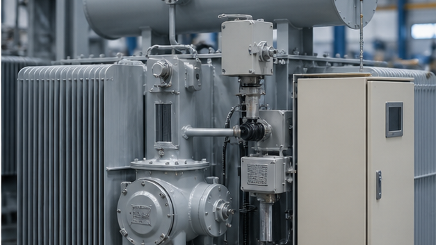
Bushings carry energized conductors through the grounded enclosure. Their voltage class, current, creepage distance, insulation technology, flange, conductor interface and test tap must match the design. Cracked porcelain, oil leakage, abnormal capacitance or rising power factor requires engineering assessment rather than cosmetic repair.
Off-circuit tap switches adjust ratio only when de-energized; on-load tap changers interrupt and transfer current during operation. Contacts, diverter components, drive mechanisms and control parts are model-specific. Timing, transition resistance and mechanical sequence must be verified after service.
Transformer Parts Function and Inspection Table
| Part group | Primary function | Evidence to check | Replacement data |
|---|---|---|---|
| Core and windings | Energy transfer and voltage transformation | Noise, resistance, ratio, insulation and deformation | Design drawing, conductor, turns, dimensions and impedance |
| Bushings | Insulated terminal through grounded tank | Cracks, leaks, capacitance and power factor | Voltage, current, BIL, creepage, flange and terminal |
| Cooling system | Remove winding and core losses | Temperature, fan/pump operation, blocked radiators | Cooling stage, flow, voltage, dimensions and materials |
| Tap changer | Adjust winding ratio | Contact wear, timing, transition resistance and drive | Model, tap range, current, sequence and control diagram |
| Protection accessories | Detect pressure, gas, level and temperature | Setpoints, contacts, wiring and functional tests | Range, contacts, mounting, logic and certificates |
Protection, Indication and Sealing Components
Liquid level, winding and oil temperature devices, pressure relief devices, sudden-pressure relays and gas relays provide condition or fault information. Their contact ratings, alarm/trip logic, sensing range, pocket dimensions and wiring diagrams must be documented. Replacing a device without checking setpoints can silently defeat protection.
Gaskets should be selected for fluid, temperature, compression and flange finish. Reusing a compressed gasket or overtightening a cover can create new leaks or distort the joint. Valves, drain plugs and sampling points must be clean, capped and positioned so maintenance does not introduce moisture.
Engineering Validation and Safety Boundary
This guide supports specification and procurement; it does not replace a project study, the applicable code, the manufacturer instructions or work by qualified electrical personnel. Verify the following before equipment selection, testing, wiring or energization:
- Confirm de-energization, isolation, grounding and stored-energy controls before access.
- Compare replacement drawings and materials with the transformer serial-specific documents.
- Assess oil compatibility and prevent moisture or particulate contamination during opening.
- Repeat applicable ratio, resistance, insulation, leak and functional tests after work.
- Update the accessory schedule, wiring diagram and maintenance baseline.
Information to Include in the RFQ
A useful quotation must be based on the same technical boundary for every supplier. Include the following information and require all deviations to be listed explicitly:
- Manufacturer, serial number, year, kVA/MVA, voltages, vector group and impedance.
- Part name, original model, drawing number, photographs and measured interfaces.
- Insulating liquid, temperature range, indoor/outdoor environment and corrosion class.
- Required contacts, wiring, alarms, setpoints and communication interfaces.
- Material certificates, routine tests, packing, warranty and installation scope.
From Technical Data to an Approved Decision
Use a staged review rather than approving the first catalogue match. Begin with magnetic core and windings, then reconcile tank, oil preservation and cooling parts with bushings, terminals and tap changers. Complete the review with protection, indication and sealing components. At each stage, record the source document, units, operating case and person responsible for approval. This prevents a value copied from an old drawing, nominal system label or unrelated product from becoming an uncontrolled design input.
Before acceptance, compare the supplier response line by line with the RFQ and mark every exception. Confirm that drawings, calculations, settings, certificates and test reports refer to the exact offered model and revision. Preserve the approved submittal, nameplate data, factory results and commissioning measurements as the maintenance baseline. If a rating, connection, environment or test condition changes, repeat the affected review rather than assuming the original conclusion remains valid.
Document control should identify revision, approval status and superseded files. Field teams should receive the same approved values used for procurement, while commissioning records should capture any authorized change made during installation. This traceability is especially important when equipment is replaced years later: the next engineer needs verified interfaces and test history, not an incomplete description copied from a purchase order.
Coverage Informed by Current Search Results
The current U.S. Google top-20 review repeatedly surfaced themes including 2. Windings, Insulation, Advancements in Transformer Cooling Techniques, How We Recycle a Transformer, 1. Laminated Core. The article addresses those user needs in an original engineering and procurement sequence; competitor brand navigation and unrelated sales material were excluded.
Related LBAJI Resources
Continue with transformer components and parts guide transformer maintenance guide LBAJI transformer range. These resources help connect the calculation or component decision to a complete transformer, switchgear, control or distribution specification.
Technical References and Further Reading
- IEC 60076-1 Power Transformers — General ratings, requirements and routine tests.
- U.S. DOE Distribution Transformers — Official transformer efficiency and regulatory resources.
- OSHA Electrical Safety — Safety requirements for work around electrical equipment.
Conclusion
Order transformer parts from verified serial-specific data, not a generic description. The correct component must preserve dielectric clearances, thermal performance, mechanical fit and protection logic; documented post-work testing then establishes a defensible new maintenance baseline.