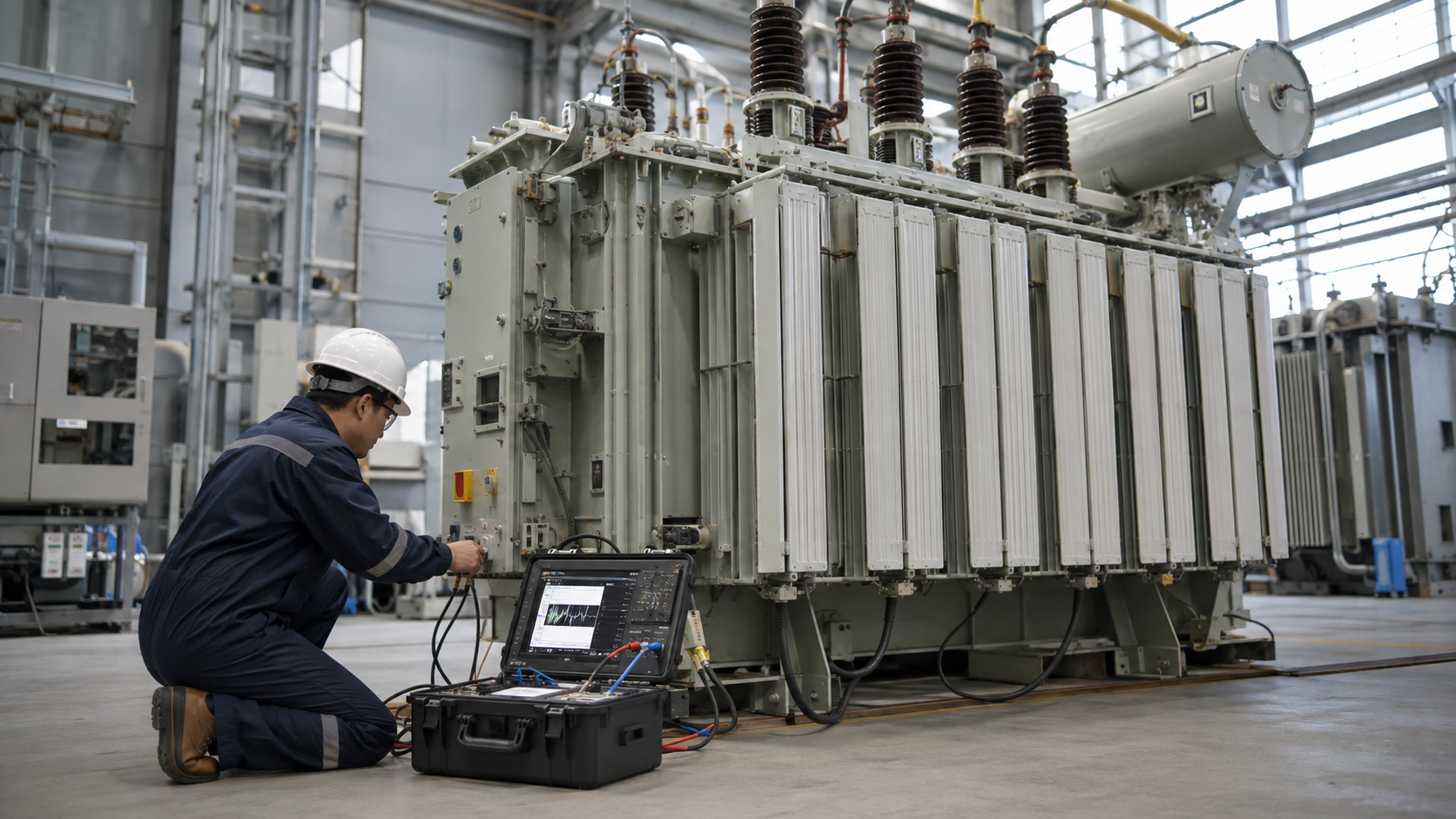
Transformer primary protection limits damage from overloads and faults while tolerating magnetizing inrush and coordinating with secondary protection; common devices include current-limiting or expulsion fuses, circuit breakers with relays, and protective switches. The correct scheme depends on transformer kVA, voltage, connection, impedance, available fault current, secondary protection and code requirements. A percentage of full-load current is only a starting point, not a complete coordination study.
Key Takeaways
- Plot inrush, damage and device curves on the same current base.
- Primary devices may not detect every low-level secondary fault quickly.
- Protection settings must match connection, grounding and downstream coordination.
What Primary Protection Must Accomplish

Primary protection should isolate internal transformer faults and severe through-faults before thermal or mechanical damage progresses. It also provides conductor and system protection required by the applicable code. The scheme must remain stable during normal energization, permitted loading and temporary motor-starting duty.
No single device provides complete protection. Temperature, pressure, gas, differential, restricted-earth-fault and secondary overcurrent functions may supplement the primary fuse or breaker depending on transformer size and criticality.
Full-Load Current, Inrush and Damage Curves
Calculate rated primary current as kVA × 1,000 ÷ V for single phase or kVA × 1,000 ÷ (√3 × line voltage) for three phase. Convert every curve to a consistent primary or secondary current base using the transformer ratio and CT ratios.
Magnetizing inrush can be many times rated current for a short interval and varies with closing angle, residual flux and system impedance. The protective curve must ride through credible inrush but remain below the transformer through-fault damage limit where coordination permits.
Fuse, Breaker and Relay Options
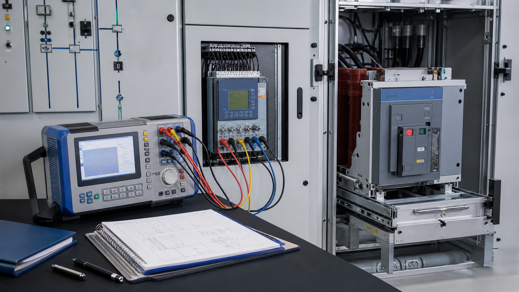
Expulsion fuses are economical and visible but vent gases and have application limits. Current-limiting fuses can reduce peak energy within their limiting range. Bayonet and backup fuses are common inside pad-mounted transformers. Every fuse requires correct voltage, current, interrupting rating and time-current curve.
A circuit breaker with numerical relays offers adjustable phase, ground, differential and communication functions. CT saturation, relay curve family, instantaneous pickup, breaker clearing time and control power must be included in coordination.
Primary Protection Option Comparison
| Option | Strength | Limitation | Best verification |
|---|---|---|---|
| Expulsion fuse | Simple and economical | Venting and limited adjustment | Time-current curve and interrupting rating |
| Current-limiting fuse | Reduces peak fault energy | Must coordinate above minimum interrupting current | Energy limitation and TCC |
| Breaker plus relay | Flexible protection and communications | Higher complexity and control power | Settings file, CT study and trip test |
| Differential relay | Fast internal-fault protection | Requires CT matching and inrush restraint | Stability and secondary-injection tests |
| Temperature/pressure devices | Detect thermal or mechanical conditions | Not conductor overcurrent protection | Setpoints and functional trip test |
Coordination with Secondary and Ground Faults
Secondary devices should clear branch and feeder faults before the primary device where selective coordination is required. Reflect secondary curves through the turns ratio and account for tolerances. A primary fuse may see only a fraction of its rating for a low-voltage ground fault, particularly with certain connections.
Grounding and winding connection control zero-sequence current. Delta-wye transformers, impedance-grounded systems and neutral CT locations require specific analysis. Differential protection is often the fastest selective method for internal faults on larger units.
Engineering Validation and Safety Boundary
This guide supports specification and procurement; it does not replace a project study, the applicable code, the manufacturer instructions or work by qualified electrical personnel. Verify the following before equipment selection, testing, wiring or energization:
- Use an approved short-circuit and coordination study, not a rule-of-thumb size.
- Include minimum and maximum fault current as well as future system changes.
- Verify fuse or breaker interrupting rating at the installation point.
- Confirm CT ratio, class, burden, polarity and saturation performance.
- Test the complete trip path from relay or device through breaker and alarms.
Information to Include in the RFQ
A useful quotation must be based on the same technical boundary for every supplier. Include the following information and require all deviations to be listed explicitly:
- Transformer kVA, voltages, phase, connection, impedance and taps.
- Maximum and minimum available fault current and system grounding.
- Primary and secondary conductor and protective-device information.
- Required relay functions, communications, control voltage and trip logic.
- Coordination study, setting calculations, test reports and spare devices.
From Technical Data to an Approved Decision
Use a staged review rather than approving the first catalogue match. Begin with what primary protection must accomplish, then reconcile full-load current, inrush and damage curves with fuse, breaker and relay options. Complete the review with coordination with secondary and ground faults. At each stage, record the source document, units, operating case and person responsible for approval. This prevents a value copied from an old drawing, nominal system label or unrelated product from becoming an uncontrolled design input.
Before acceptance, compare the supplier response line by line with the RFQ and mark every exception. Confirm that drawings, calculations, settings, certificates and test reports refer to the exact offered model and revision. Preserve the approved submittal, nameplate data, factory results and commissioning measurements as the maintenance baseline. If a rating, connection, environment or test condition changes, repeat the affected review rather than assuming the original conclusion remains valid.
Document control should identify revision, approval status and superseded files. Field teams should receive the same approved values used for procurement, while commissioning records should capture any authorized change made during installation. This traceability is especially important when equipment is replaced years later: the next engineer needs verified interfaces and test history, not an incomplete description copied from a purchase order.
Coverage Informed by Current Search Results
The current U.S. Google top-20 review repeatedly surfaced themes including Understanding NEC Table 450.3(B), You may also like, Example 1: Primary-Only Protection, Protecting Primary Conductors, National Electrical Code Considerations for Existing vs. New Work. The article addresses those user needs in an original engineering and procurement sequence; competitor brand navigation and unrelated sales material were excluded.
Related LBAJI Resources
Continue with transformer protection guide transformer fuse guide medium-voltage switchgear. These resources help connect the calculation or component decision to a complete transformer, switchgear, control or distribution specification.
Technical References and Further Reading
- IEC 60076-5 — Transformer ability to withstand short circuit.
- IEEE Standards Association — Transformer protection and device standards.
- NFPA Codes and Standards — Electrical installation and overcurrent rules.
Conclusion
Transformer primary protection is a curve-coordination problem bounded by inrush, damage, fault levels and grounding. Select and test the complete scheme—including CTs, relays, trip circuit and downstream devices—rather than choosing a fuse or breaker from full-load current alone.