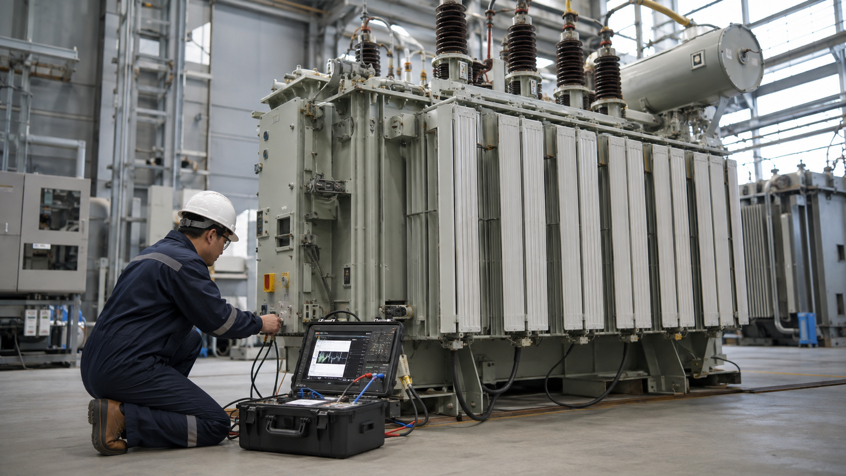
A transformer fuse interrupts a fault when current and time reach the fuse’s operating range. It can protect a transformer from some internal faults, limit damage to connected equipment, and help isolate one failed unit without unnecessarily disconnecting the entire upstream circuit. It cannot be selected from transformer kVA alone. The engineer must first establish the installation voltage, full-load current, available fault current, transformer inrush, primary and secondary protection arrangement, applicable code, and coordination with other devices. The arithmetic examples below calculate normal current only; they are not recommended fuse ampere ratings.
What a transformer fuse does—and does not do
A fuse is a one-time overcurrent device. Its element heats and opens when its time-current characteristic is exceeded. Transformer protection is more involved than simply preventing the winding from carrying its rated load. Energization can produce a short inrush event well above steady-state current, while a genuine internal fault must clear before damage grows. Downstream conductors and equipment also require protection appropriate to their own ratings and installation. The fuse, therefore, has to fit a protection system, not just a nameplate.
In some schemes a primary fuse addresses transformer faults while a secondary breaker or fuse provides secondary conductor and load protection. In others, a primary protective device must also satisfy specific conditions for secondary protection. The exact arrangement depends on the transformer, wiring method, voltage, equipment listing, local code adoption, and authority having jurisdiction. The NFPA NEC 450.3 code-development material shows why primary and secondary protection are treated separately; it is not a substitute for the adopted code text or an approved design.
Start by identifying the application
Search results for “transformer fuse” mix several equipment classes. Applying a medium-voltage distribution-fuse table to a low-voltage control transformer—or the reverse—would be an unsafe shortcut. Use this comparison to define the design problem before considering a part number.
| Application | Typical protection question | Information that changes selection | Do not assume |
|---|---|---|---|
| Control transformer inside a panel | How are small primary and secondary circuits protected? | Primary/secondary voltage, VA rating, winding arrangement, panel listing, conductor size, inrush and local code | A distribution-transformer fuse link or rule fits the panel |
| Low-voltage power transformer | Which device protects the transformer and which protects secondary conductors? | kVA, single/three-phase rating, voltage, impedance, fault study, breaker/fuse curves and installation | One primary fuse automatically protects every secondary conductor |
| Medium-voltage distribution transformer | How should a primary fuse coordinate with upstream and downstream protection? | System voltage, available fault current, transformer damage and inrush curves, grounding, mounting and fuse family | A catalogue’s kVA row is final approval |
The voltage boundary matters. IEC 60282-1:2020 addresses high-voltage current-limiting fuses for systems above 1,000 V. It should not be presented as a universal low-voltage sizing rule. The applicable edition, local adoption and equipment-specific instructions need to be confirmed for each project.
Calculate full-load current before considering a fuse rating
Transformer rated current is a useful starting input. For a single-phase transformer, use I = VA ÷ V. For a three-phase transformer, use I = VA ÷ (√3 × VLL), where VLL is line-to-line voltage. Use the winding voltage corresponding to the side being evaluated, and use VA rather than watts. If the nameplate gives kVA, multiply by 1,000 first.
For example, a 5 kVA single-phase transformer on a 240 V winding has nominal full-load current of 5,000 ÷ 240 = 20.8 A. A 75 kVA three-phase transformer on a 480 V line-to-line winding has nominal full-load current of 75,000 ÷ (1.732 × 480) = 90.2 A. These calculations say nothing by themselves about acceptable fuse size, interrupting capacity, inrush withstand, conductor protection or coordination. Do not turn either answer into a purchase specification by rounding up to the next catalogue fuse.
Repeat the calculation independently for the primary and secondary sides. The current changes with voltage even when kVA is the same. For an actual selection, confirm which voltage the transformer will see, tap settings, intended loading, grounding, and the selected device’s published time-current curve. Readers comparing common capacity examples can use our 63 kVA load guide and 75 kVA current guide; those pages explain load arithmetic, not fuse approval.
Transformer fuse types are not interchangeable
| Device family | Where it may be considered | Key verification before use |
|---|---|---|
| Low-voltage cartridge fuse | Listed low-voltage control or power circuits | Fuse class, voltage and interrupting ratings, holder/listing, time-current curve and equipment instructions |
| Expulsion fuse link | Suitable outdoor distribution arrangements | Cutout compatibility, voltage, interrupting duty, location and utility coordination practice |
| Medium-voltage current-limiting fuse | Suitable switchgear or transformer protection schemes | Fuse family, minimum interrupting current, mounting, inrush, fault study and manufacturer application data |
| Bayonet-style fuse | Compatible liquid-filled transformer designs | Transformer manufacturer’s approved assembly and required backup protection |
These rows describe possible application families, not a substitution list. A fuse that physically fits a holder can still be wrong for the circuit. The Mersen medium-voltage transformer-protection application note illustrates why fuse-family and application conditions must stay together. Its examples should not be transferred to another manufacturer’s product without checking that product’s data.
A practical selection workflow
1. Collect the transformer and system records
Record the transformer kVA, phase count, primary and secondary voltages, impedance, tap position, connection, cooling method, installation environment and manufacturer. Add a one-line diagram showing all upstream and downstream protective devices. For a retrofit, record the existing fuse type and holder but do not assume the old part was correct. Ask whether the transformer is a control unit, a stand-alone low-voltage transformer, a pad-mounted unit or part of an integrated substation.
2. Establish fault duty and device ratings
Obtain the available short-circuit current at the proposed device location. Check the proposed fuse’s voltage rating, interrupting rating, applicable current range, and installation/listing requirements against that study. A device’s normal-current rating does not establish that it can safely interrupt the available fault. If the fault study is absent, the design is not ready for final fuse selection.
3. Compare inrush and time-current curves
Transformer energization can produce a short-duration current above full load. Compare the manufacturer’s expected inrush information with the candidate fuse’s time-current characteristic so normal energization does not cause unnecessary operation. Then compare the curve with transformer thermal/damage information and the downstream and upstream device curves. The aim is to clear faults while avoiding unnecessary loss of a wider section of the installation. The coordination check must use the actual device families and settings, not a generic “slow-blow” label.
4. Resolve primary versus secondary responsibilities
Identify whether the primary device protects only the transformer or also participates in secondary protection under the adopted rules. Verify secondary conductor and equipment protection separately. A secondary main device may be necessary; a secondary fault can behave differently from a primary fault because transformer impedance limits current. This is one reason that a primary fuse chosen solely from the primary winding current can leave gaps in a complete protection design.
5. Check physical compatibility and operating conditions
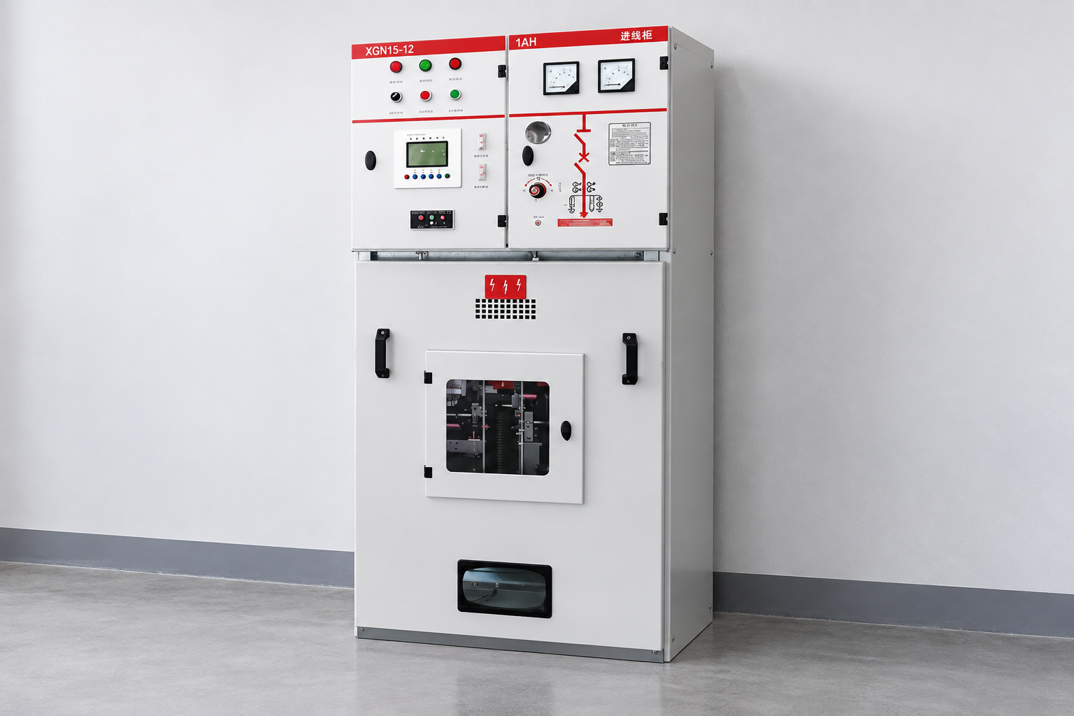
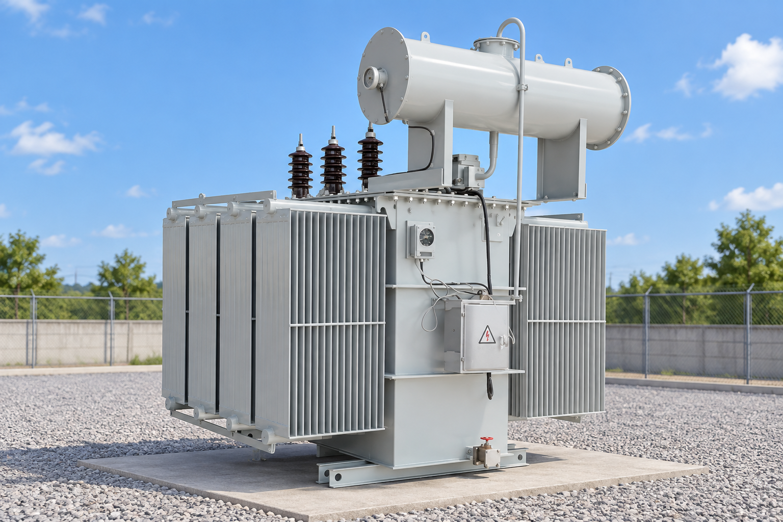
Confirm the fuse holder, mounting, enclosure, ambient temperature, altitude, accessibility and replacement procedure. Outdoor cutouts, indoor switchgear compartments and transformer-integrated fuse wells have different constraints. For equipment represented by LBAJI’s YB27-12 prefabricated substation or ring-main units, request the project-specific electrical drawings and approved protective-device schedule. An equipment photo is not evidence that a particular fuse model or rating is supplied.
For equipment context only, the following product exterior is not evidence of an internal fuse or rating.
6. Document the final engineering decision
Record the chosen manufacturer’s exact part number, voltage and interrupting ratings, time-current curve revision, coordination study, applicable code edition, installation instruction and approval. Keep these with the one-line diagram. A table of “transformer kVA to fuse amps” can be useful only when its assumptions and fuse family match the project; it cannot replace these checks.
Educational background: protection devices
TU Delft OpenCourseWare’s “7.1.1 Protection devices” lecture provides general low-voltage grid background on protective devices. It is not a transformer-specific fuse-sizing method and does not approve a medium-voltage fuse selection; use the project study, adopted rules and equipment instructions for that decision.
View the TU Delft OpenCourseWare lecture.
Common mistakes during transformer fuse sizing
Using load current as the fuse rating. Full-load current is an input, not an output. The selected device must also tolerate permitted inrush and operating conditions while clearing faults appropriately. Copying a table across voltage classes. A medium-voltage distribution table cannot govern a low-voltage control circuit. Ignoring available fault current. An inadequate interrupting rating can make a device unsafe even if its ampere number appears reasonable. Ignoring the secondary side. Primary protection does not automatically complete conductor and equipment protection downstream. Replacing with a different fuse family. Similar-looking devices can have materially different curves and mounting requirements.
Repeated fuse operation is a symptom to investigate, not a reason to fit a larger fuse. Follow the site’s electrical safety procedure, isolate and verify the circuit as required, and have a qualified person identify the underlying fault before re-energization. For related diagnostic context, see our transformer testing guide and transformer protection overview.
What to include in a transformer-fuse RFQ
Send the transformer nameplate and datasheet; primary and secondary voltage; phase count and winding connection; system one-line diagram; available short-circuit current; grounding and conductor details; the proposed installation or holder; environmental conditions; upstream/downstream device models and settings; and the governing code or utility specification. Ask the supplier to identify the exact fuse family, approved holder, voltage and interrupting ratings, published curve, replacement procedure and any required backup device. Request a documented coordination review rather than a bare ampere recommendation. If the project uses LBAJI transformer or substation equipment, LBAJI can use this package to confirm which project-specific protective-device information is available; no particular fuse model is implied by this guide.
Frequently asked questions
Can I size a transformer fuse from kVA alone?
No. kVA and voltage let you calculate nominal current. Final selection also depends on voltage class, fault duty, inrush, time-current coordination, primary/secondary responsibilities, installation and applicable rules.
Is the primary fuse enough to protect secondary conductors?
Not as a general assumption. The protection arrangement must be checked against the transformer connection, circuit design and adopted code. Secondary overcurrent protection may be required.
Why does a transformer fuse open at energization?
Possible causes include normal inrush exceeding an unsuitable fuse curve, an actual fault, incorrect wiring or another system problem. Do not bypass protection or install a larger fuse before a qualified person investigates the cause.
Can I replace an expulsion link with a current-limiting fuse?
Not merely because both are fuses. Their operating characteristics, mounting and application limits differ. Use only a design and equipment combination verified by the responsible engineer and manufacturer.
Bottom line: calculate transformer current, then use the project fault study, device curves, equipment instructions and governing rules to choose and document the fuse. There is no responsible universal transformer-fuse ampere chart.