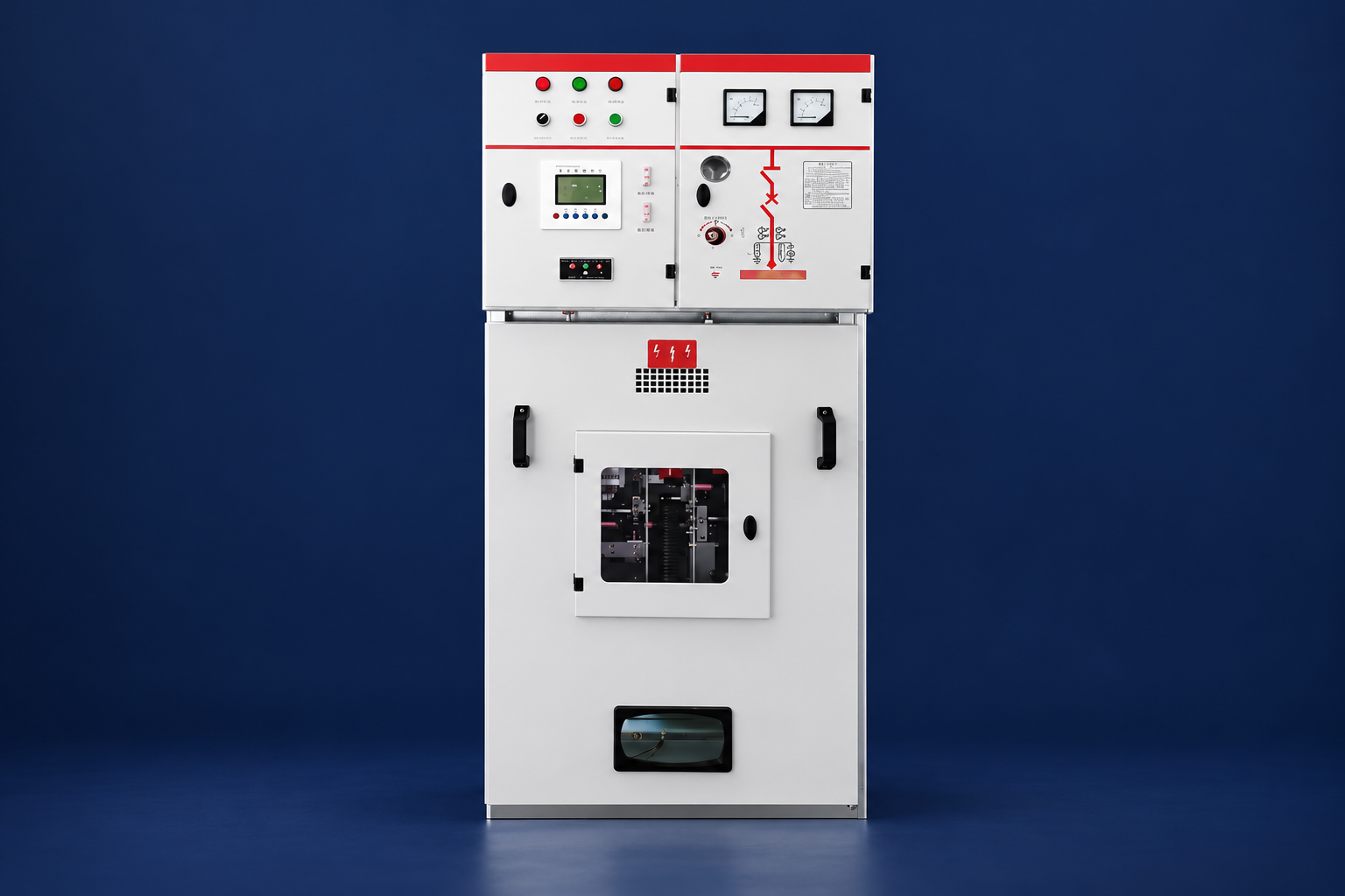
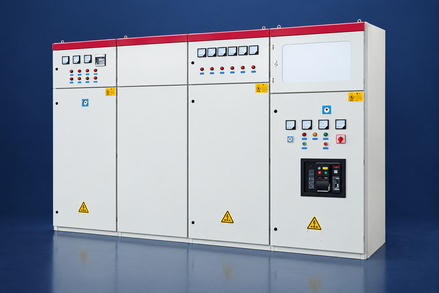
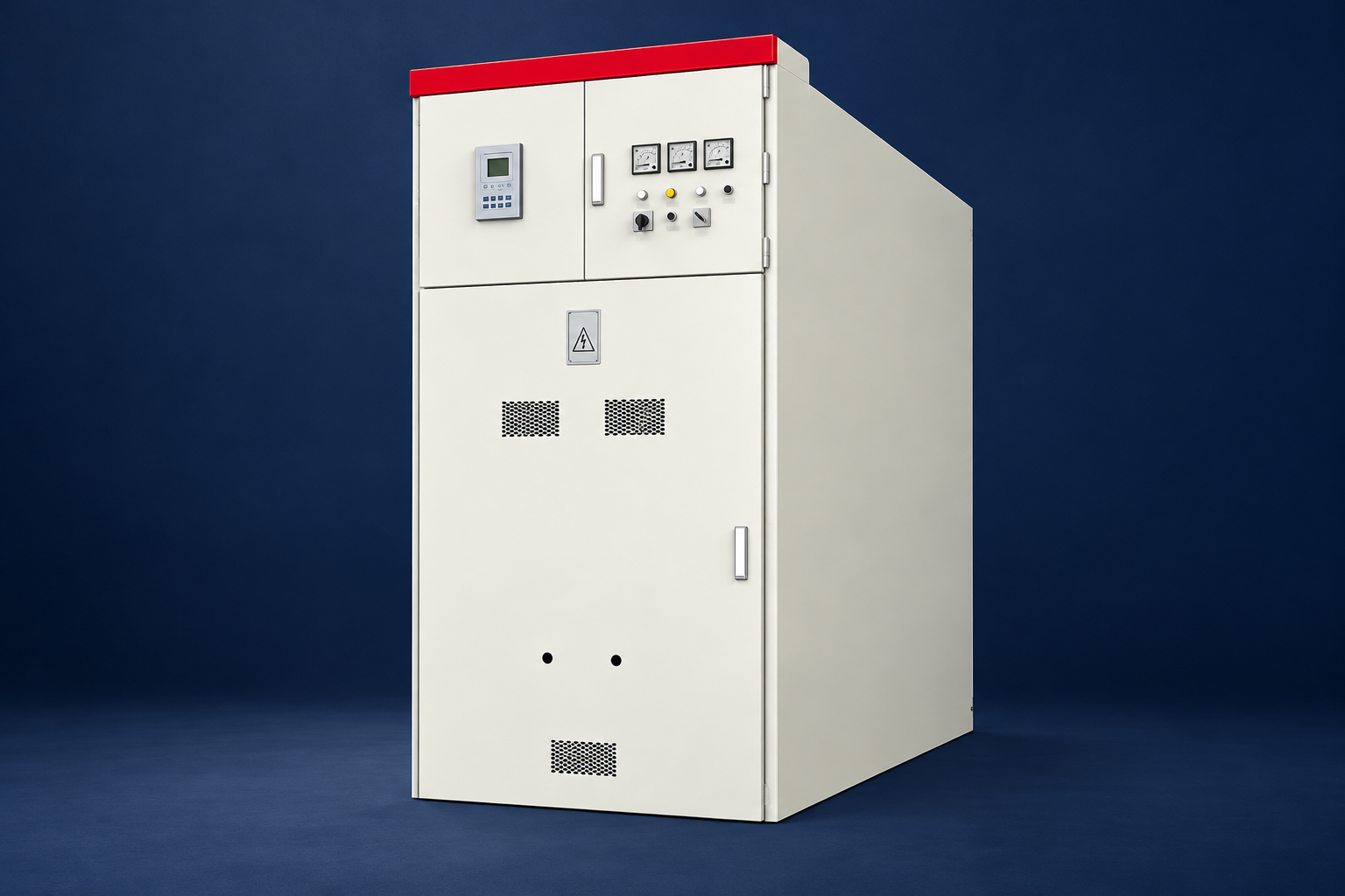
Medium voltage switchgear brings together the switching, protection, measurement and isolation equipment used to control distribution feeders. It may appear as a metal-clad breaker lineup, a metal-enclosed assembly or a compact ring-main unit. The right choice depends on the system study, operating scheme, applicable project standards, installation environment and maintenance plan. “Medium voltage” alone is not enough to select equipment: the specification must state the actual system and equipment ratings, fault duty, construction, protection and test requirements. For equipment relationships across a complete site, see our substation design and layout guide.
What medium voltage switchgear does
A switchgear assembly connects a source, bus and outgoing circuits while allowing operators and protection systems to control faults and planned switching. Depending on the design, the assembly can include circuit breakers or load-break switches, busbars, current and voltage transformers, protective relays, metering, control wiring, cable terminations and interlocks. The assembly is selected and tested as a coordinated system; a breaker’s rating alone does not establish that a complete lineup is suitable.
In normal service, the assembly carries the assigned load and permits switching within its design duties. During a fault, instrument transformers provide measurements to the relay, the relay operates the trip circuit and the circuit breaker interrupts the fault current within its rated duty. Isolation and earthing arrangements then support the site’s approved safety procedure. Exact operating steps belong in the manufacturer’s instructions and the facility’s switching rules.
For a broad visual introduction to how electrical substations fit into a power network, see this educational overview:
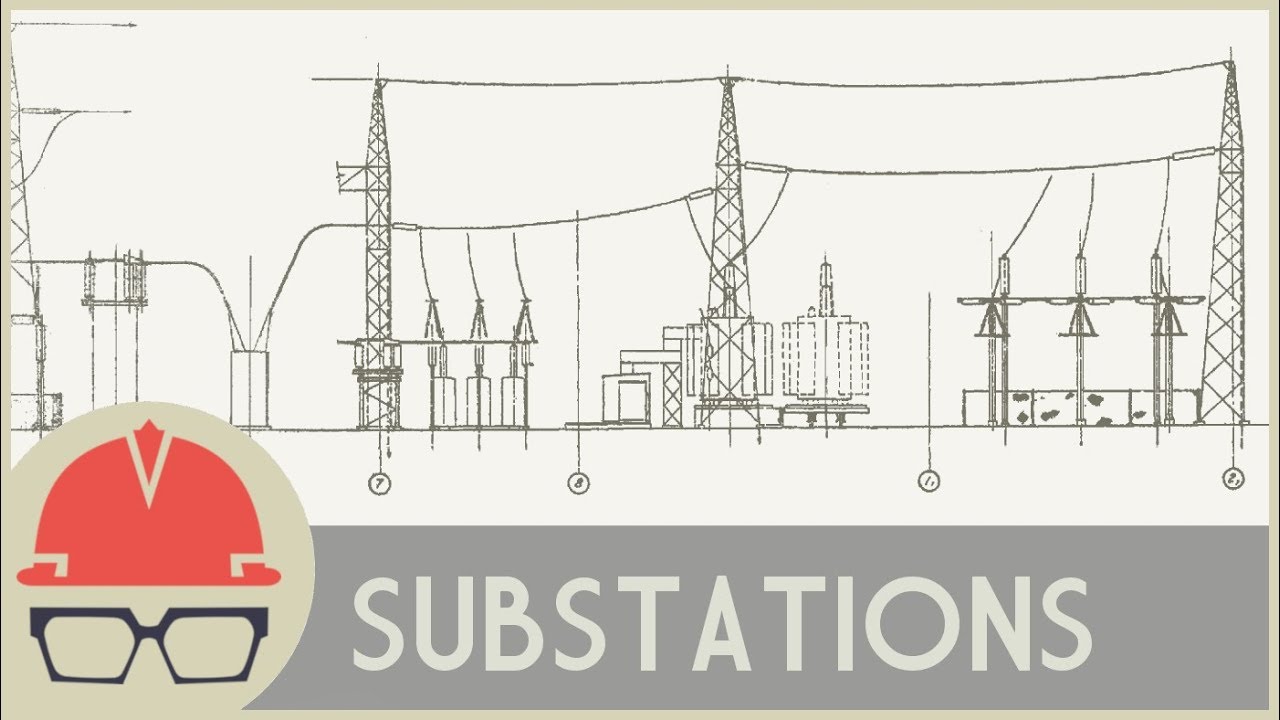
Watch “How Do Substations Work?” by Practical Engineering on YouTube. The video provides substation context; it does not replace a switchgear design, operating procedure or safety review.
Separate insulation type, enclosure construction and feeder function
Switchgear labels describe different design questions. AIS, GIS and solid insulation describe how energized parts are insulated. Metal-clad and metal-enclosed describe construction under a specific standard. A breaker lineup, switch-fuse unit or ring-main unit describes a functional arrangement. These labels overlap, so compare the offered assembly against the complete specification rather than treating one label as a complete description.
| Design family | Typical reason to consider it | What to confirm before selection |
|---|---|---|
| Air-insulated switchgear (AIS) | Room is available for the required clearances and the project values accessible compartments and conventional arrangements. | Clearances, access, contamination, humidity, altitude, cable space and the exact tested assembly. |
| Gas-insulated or other sealed designs (GIS) | A compact, enclosed arrangement is important or the installation needs protection from its surrounding environment. | Insulating medium, sealed-compartment monitoring, service access, end-of-life handling, expansion plan and applicable tests. |
| Solid-insulated or hybrid designs | The project is considering an alternative combination of insulation and enclosure methods. | Interface design, partial-discharge evidence, repair method, spare parts, environmental conditions and the limits of type-test coverage. |
No insulation family is automatically the safest, lowest-cost or best choice. Compare installed footprint, cable access, inspection and service strategy, operating conditions, evidence for the offered model and the full-life cost using the same project assumptions. For more on air-insulated construction, see our air-insulated medium-voltage switchgear guide.
Metal-clad versus metal-enclosed switchgear
Terms such as “metal-clad” and “metal-enclosed” have meaning within their applicable standards. IEEE Std C37.20.2-2025 covers metal-clad medium-voltage switchgear with drawout electrically operated circuit breakers and grounded metal barriers that compartmentalize major components. IEC 62271-200:2021, including Amendment 1:2024, addresses AC metal-enclosed assemblies above 1 kV and up to 52 kV. The terms are not interchangeable shorthand for any steel cabinet, and one standard’s construction label does not prove compliance with another.
For projects using IEC requirements, the current offer should identify the applicable assembly standard, edition and amendments, rated characteristics and relevant type-test evidence. For projects using ANSI/IEEE requirements, call out the requested standard and edition in the enquiry. Where an owner or utility has additional specifications, list them separately and resolve conflicts before the design is frozen.
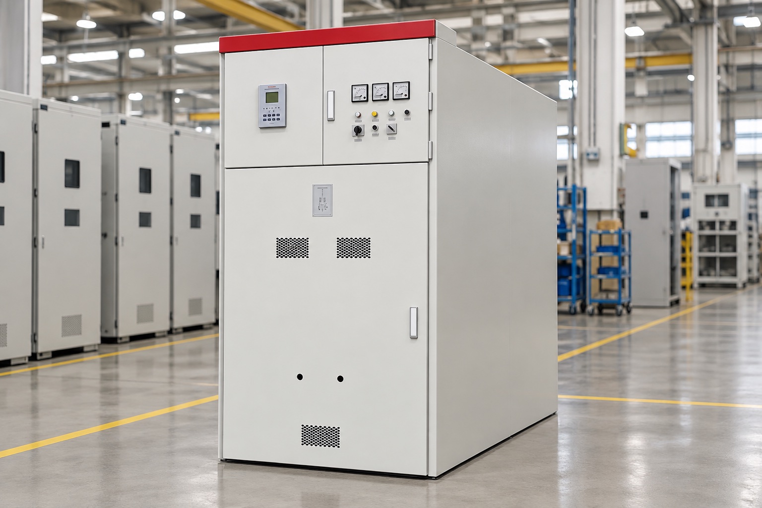
For a product example, LBAJI’s KYN28A-12 metal-clad switchgear is listed as a 12 kV-class product. A higher-voltage product example is the KYN61-40.5 metal-enclosed switchgear. These pages describe product offerings; the project engineer still needs the exact approved ratings, drawings and test documentation for the proposed configuration.
Breaker lineups, switches and ring-main units
A breaker lineup is often considered when several feeders need independent protection, measurement and control. A withdrawable breaker can support a defined connected, test and isolated arrangement, but the complete compartment, shutters, interlocks, earthing device and operating mechanism must match the specified assembly. The breaker’s continuous-current, interrupting and operating-duty ratings must match the system study and the application.
A ring-main unit (RMU) is a compact distribution arrangement commonly used for ring or radial feeder schemes. Its ways may use load-break switches, fuse-switch combinations or circuit breakers with relays. The right arrangement depends on fault-clearing responsibilities, transformer protection, network operating philosophy, remote control and planned extension. A sealed enclosure or a small footprint does not by itself confirm suitability for a particular fault level or switching duty.
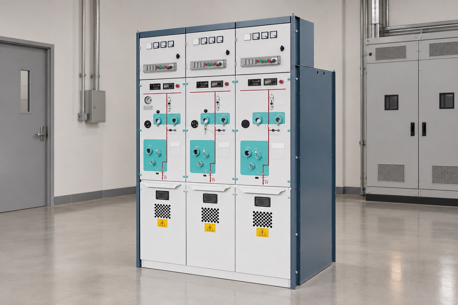
Compare the LBHB-12(V)/630-20 ring-main unit and HC-40.5 ring-network switchgear as product examples only. Request drawings and guaranteed data for the required voltage class, feeder count, switching devices, protection, cable interfaces and environmental conditions.
Ratings and project inputs to compare
Use system studies and the project specification to establish the required ratings. Do not select a lineup from the nominal voltage or transformer kVA alone. Ask the supplier to return a completed schedule that states each offered value and identifies any deviation.
Where earth-fault protection is specified, include the sensor window, conductor path, residual-current pickup and relay input in the lineup review. Our core-balance current transformer guide explains these coordination checks.
| Input or rating | Project information to provide | Offer evidence to request |
|---|---|---|
| System and insulation | Nominal system voltage, equipment rated voltage, frequency, grounding method and insulation coordination requirements. | Nameplate schedule and dielectric withstand ratings under the specified standard. |
| Continuous load | Maximum operating load, load profile, spare feeders, expected growth and ambient/site conditions. | Bus and feeder current ratings and the service-condition assumptions used for the offer. |
| Short-circuit duty | Maximum and minimum fault levels, clearing time, source contribution and protection philosophy from the approved study. | Breaker making and breaking duties plus assembly short-time and peak withstand evidence, as applicable. |
| Switching application | Motor, transformer, cable, capacitor or other switching duties and the required operating sequence. | Device selection, declared switching duties and supporting test documentation for the offered configuration. |
| Protection and measurement | CT/VT ratios and accuracy needs, relay functions, control voltage, metering, communications and required signals. | Wiring diagrams, relay/CT/VT schedule, interlock logic, terminal plan and communication details. |
| Enclosure and safety | Indoor/outdoor location, access sides, room or kiosk layout, cable entry, ventilation, altitude, seismic and corrosion conditions. | Enclosure details, declared accessibility and internal-arc classification where specified, installation limits and matching test evidence. |
Internal-arc classification applies only to the tested configuration and stated access sides, current, duration and installation arrangement. Verify that doors, pressure-relief paths, room geometry and exhaust routing match the evidence. Arc-resistant construction is not permission to work on energized equipment; personnel must follow applicable electrical-safety rules and site procedures.
A practical selection sequence
- Confirm the supply and one-line diagram. Identify sources, transformer interfaces, bus sections, tie breakers, feeders, loads, generation and the normal and contingency operating states.
- Complete the system studies. Have qualified project engineers establish load, fault levels, protection coordination, grounding, switching duties and any required insulation coordination. Provide assumptions and study revisions with the enquiry.
- Choose the functional arrangement. Decide whether the project needs a breaker lineup, switch-fuse arrangement, RMU or another configuration. Define feeders, metering, future bays and the required service continuity during maintenance.
- Compare construction against the site. Check room footprint, front/rear access, lifting route, cable bend space, foundation, ventilation, arc-pressure routing, moisture, contamination, altitude and corrosion exposure.
- Set protection and control requirements. Coordinate relay functions, CT/VT data, trip and close circuits, interlocks, local/remote controls, alarms, time synchronization and communication protocols before drawings are approved.
- Review the exact offer. Compare every proposed rating and exception against the request. Confirm which assembly and accessories are covered by each type-test report; do not infer coverage from a similar product family or isolated component certificate.
- Plan factory and site verification. Agree inspection points, routine tests, witnessed factory tests if required, document hold points, commissioning tests, spares, training and maintenance instructions before placing the order.
What to include in a switchgear enquiry
A complete enquiry reduces avoidable substitutions and helps engineering teams compare like for like. Attach the current single-line diagram, load and feeder schedule, system-study fault levels, grounding details, required standards and editions, indoor/outdoor conditions, layout and cable-entry drawings, operating sequence, protection/CT/VT schedule, control and communications requirements, access and internal-arc needs, testing scope, document list, spare-parts requirements and delivery constraints. Mark every value as required, preliminary or supplier-proposed.
Ask for a deviation list rather than accepting a brochure as the compliance response. The returned schedule should state offered ratings, construction and standard edition, relay and instrument-transformer data, cable interfaces, dimensions, weights, access clearances, pressure-relief arrangement if applicable, type-test references, routine-test scope and exceptions. Require approval of drawings and interface points before manufacturing.
Compare total project cost on a consistent basis. Include switchgear, protection and metering, control power, cable terminations, civil and room changes, commissioning, training, spares, maintenance access, expected outage implications and end-of-life handling. A lower equipment price may not mean a lower installed or lifecycle cost if it shifts work to the site. Our power distribution system design guide covers the broader system-planning context.
Testing, commissioning and maintenance
Factory inspection and acceptance testing should follow the project specification and the applicable product standard. Depending on the offered design and scope, checks may cover appearance and identification, wiring, mechanical operation, interlocks, main-circuit resistance, dielectric tests, relay functions, trip/close paths, metering and communication signals. Type tests, routine tests and project FAT are different kinds of evidence; ask which test report applies to the exact assembly and which checks will be repeated at site.
Before energization, qualified personnel should verify approved drawings, grounding, cable terminations, phasing, instrument-transformer circuits, protection settings, interlocks, trip circuits, remote indications and alarms under the site commissioning plan. Maintenance intervals and methods must follow the manufacturer’s current instructions, operating duty, inspection findings and site risk assessment; do not apply a generic interval to every switchgear design. See our substation maintenance guide for related site-maintenance checks.
Relevant standards and project documents
Standards define scope and requirements; they do not, by themselves, prove that a particular offered assembly complies. Relevant starting points include IEC 62271-1:2017 with Amendment 1:2021 for common AC switchgear specifications, IEC 62271-200:2021 with Amendment 1:2024 for AC metal-enclosed assemblies, IEEE C37.20.2-2025 for metal-clad switchgear, and IEEE C37.121-2020 for switchgear-unit-substation coordination. Confirm the current edition adopted by the owner, jurisdiction and utility, plus all applicable component standards and project specifications.
Frequently Asked Questions
What is medium voltage switchgear used for?
It switches, protects, measures and isolates distribution circuits between a source and downstream feeders. The required arrangement depends on system studies, loads, protection and site conditions.
What is the difference between metal-clad and metal-enclosed switchgear?
Metal-clad is a defined construction under its applicable standard, generally with compartmentalized components and drawout breakers under IEEE C37.20.2. Metal-enclosed is a broader term in other standards. Specify the exact standard and tested assembly.
Should I choose AIS or GIS?
Compare footprint, service access, environmental conditions, insulation medium, maintenance, end-of-life handling, expansion and the exact test evidence. Neither type is best for every project.
How do I size medium voltage switchgear?
Use the approved load and short-circuit studies, insulation requirements, switching duties, protection scheme and service conditions. A transformer’s kVA rating alone is not sufficient.
What information should I send for a switchgear quotation?
Provide the single-line diagram, voltage and frequency, grounding, load and fault data, feeder arrangement, protection and CT/VT schedule, cable interfaces, environmental conditions, standards, safety requirements and testing/documentation scope.
Conclusion
Choose medium voltage switchgear from the system and project requirements, then compare complete assemblies and their evidence. A clear one-line diagram, fault study, ratings schedule, standard edition, installation plan and test scope make it easier to select a design that can be reviewed, installed and maintained as intended.