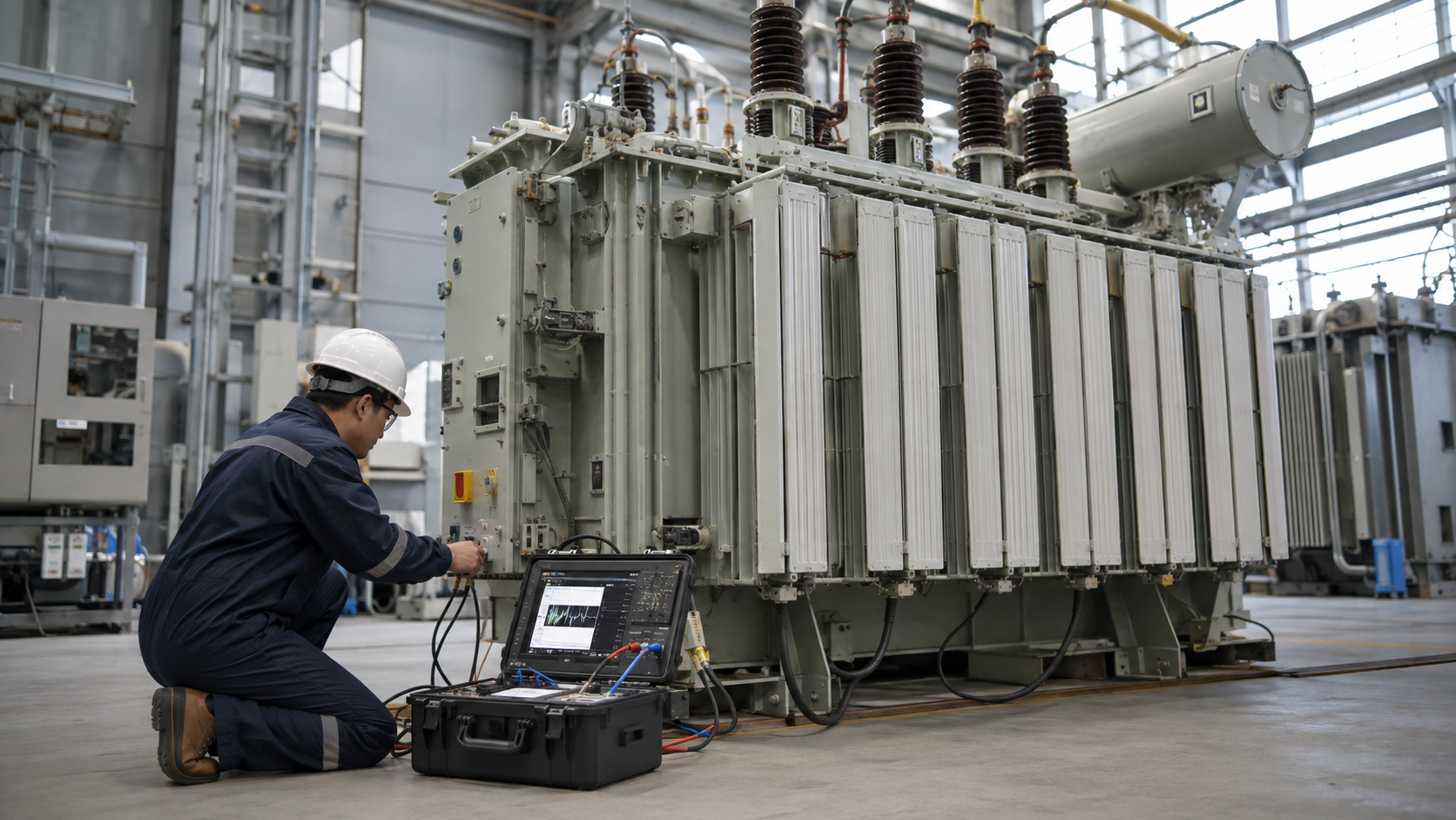
An autotransformer is a transformer with one continuous winding and one or more taps, so part of the winding is common to both input and output; it can change voltage efficiently and compactly but normally does not provide galvanic isolation.
Shared-winding principle
The common section carries the difference between primary and secondary currents, while the series section carries load current according to the connection. Power transfers partly by induction and partly by direct electrical conduction through the shared winding.
Step-up and step-down operation
Connecting the source across the full winding and the load across a tap gives step-down operation; reversing the relationship gives step-up operation within the designed ratings. Polarity and tap connection determine whether voltages add or subtract.
Why size and losses can be lower
When voltage ratio is close to one, only part of total apparent power is transformed inductively. This can reduce copper, size, mass, losses, voltage drop, and cost compared with a two-winding transformer of the same through-power.
The isolation limitation
Input and output are electrically connected. A fault, surge, neutral problem, or insulation failure can transfer between sides in ways an isolating transformer would prevent. Never substitute an autotransformer where safety, grounding, noise control, or a separately derived system requires isolation.
Typical applications
Applications include motor starting, modest voltage correction, interconnecting systems with similar voltages, laboratory variable supplies, railway systems, and utility voltage regulation. Each requires review of grounding, fault duty, tap range, and protection.
Variac and variable autotransformers
A variable autotransformer uses a movable contact on an exposed or accessible winding to provide adjustable AC voltage. Its output can remain hazardous at a low indicated voltage and may exceed nominal input near the high end. It is not an isolation device.
Ratings and protection
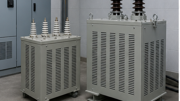
Specify input and output voltage range, frequency, through-kVA, winding or transformed kVA, current at each terminal, taps, impedance, short-circuit duty, insulation level, temperature rise, enclosure, cooling, and grounding. Coordinate protection with inrush and fault current.
Autotransformer versus two-winding transformer
Choose an autotransformer for efficient conversion between nearby voltages when electrical connection is acceptable. Choose a two-winding unit when isolation, independent grounding, ratio, fault containment, or system requirements outweigh size and efficiency advantages.
A worked example: 240 V to 120 V
Consider an ideal single-phase autotransformer supplying a 120 V, 10 A load from a 240 V source. The load apparent power is 120 × 10 = 1,200 VA. Ignoring losses and excitation current, source current is 1,200 ÷ 240 = 5 A. A tap halfway along the effective turns provides the required voltage relationship. These figures explain the principle; they are not a construction drawing or a rating for an arbitrary winding.
The section between the 240 V terminal and the 120 V tap carries 5 A. At the tap, current divides between the load and the common winding section. In this ideal case the common-section current has magnitude 5 A and flows in the opposing direction needed for ampere-turn balance. It is therefore incorrect to say that every part of an autotransformer winding carries the full 10 A load current.
For this example the series-section voltage is 120 V, so its transformed apparent power is 120 × 5 = 600 VA, while the load receives 1,200 VA. The remainder is transferred through the direct electrical connection. This shared transfer explains the material advantage. Real units must additionally allow for winding heating, contact ratings, insulation, loss and fault duty; the arithmetic alone cannot establish a commercial rating.
What changes when the voltage ratio is close to one?
For an ideal step-down autotransformer with k = Vlow/Vhigh, the inductively transformed fraction of through-power is 1 − k. Changing 240 V to 220 V gives k ≈ 0.917, so the fraction is about 8.3%. Changing 240 V to 24 V gives a fraction of 90%. Consequently, the shared-winding advantage is strongest for a modest voltage change and becomes smaller as the ratio grows.
This does not mean that a 240-to-220 V device can be substituted for a 240-to-24 V supply by selecting another terminal. The winding, current path and insulation were designed for specific connections. It also does not prove a fixed efficiency or price saving. Compare tested losses and the complete offered assembly, including enclosure, protection and tap equipment, against the two-winding alternative.
Autotransformer versus isolation transformer
| Decision | Autotransformer | Separate-winding transformer |
|---|---|---|
| Electrical connection between source and load | Shared winding provides a conductive path | Windings are electrically separate by design |
| Modest voltage correction | Often a compact solution where shared grounding is acceptable | Possible, generally with more material for the same through-power |
| Independent secondary reference | Cannot be assumed | Can support a separately derived arrangement when correctly designed |
| Variable laboratory output | Movable tap can adjust voltage; output remains connected to mains | Isolation alone does not imply adjustable output |
| Fault current | Often low impedance; system study remains necessary | Depends on its stated impedance and the upstream supply |
The OpenStax discussion of electrical safety and isolation helps explain the role of a separated circuit. A low output-voltage setting on a variable autotransformer is not proof that either output conductor is safe relative to earth. An installation needing protective separation must use equipment expressly designed for that purpose.
How an autotransformer motor starter works
A reduced-voltage starter applies a selected fraction of supply voltage during acceleration and then transfers the motor to its running connection. In the simplified model, if the motor receives a voltage fraction k, its locked-rotor current is approximately k times the direct-on-line current, while the supply current through an ideal autotransformer is approximately k squared times that current. Starting torque also falls approximately with the square of voltage.
The benefit is reduced supply disturbance, but the lower torque must still accelerate the actual load. A heavily loaded conveyor or high-inertia machine cannot be assessed only by an appealing current reduction. The design must account for acceleration time, transition method, starts per hour, thermal duty and the mechanical load curve. These simplified relationships are screening tools; the motor manufacturer’s data and the complete starter design govern selection.
Variable output and current limits
A variable autotransformer uses a contact that moves along a prepared winding surface. Output can usually be varied over its specified range, and some designs include a range above nominal input voltage. Read the exact scale and manual. The contact, winding and terminal current limits continue to apply at reduced voltage: lowering output voltage does not necessarily permit proportionally higher output current.
For example, a unit limited to 5 A cannot automatically deliver 50 A when its output is turned down to one tenth of rated voltage. The common mistake is to treat the entire nameplate VA value as available at every knob position. The load, brush contact and thermal design must be checked. Variable autotransformers also do not convert AC to DC or change frequency.
What to put on a purchase specification
Distinguish the terminal through-kVA from the internally transformed kVA on every offer. Quoting one while the buyer expects the other can make two proposals appear comparable when their actual load capacities differ.
State whether the duty is continuous voltage correction, variable test supply, motor starting or network interconnection. Identify all terminal voltages and current ratings, phase and frequency, tap range, isolation requirement, neutral arrangement and permissible temperature rise. Include the expected load profile and any starting or cyclic duty. A motor-starting rating cannot simply be treated as continuous kVA.
Ask for the actual connection drawing, impedance, loss data, protective-device requirements and installation instructions. Check the output range under load and the permitted supply variation. For industrial applications, the review should establish how a winding or neutral fault affects connected equipment. The OSHA electrical installation requirements reinforce the need to use equipment within its intended ratings and instructions.
Related transformer guides and product context
Review the transformer fundamentals guide for the underlying principles. For adjacent questions, read What Does a Step-Down Transformer Do? Operation and Uses and What Is an Isolating Transformer? Safety, Uses and Selection. For distribution-equipment specifications, see the 35 kV oil-immersed power transformer; confirm the actual product scope and ratings before using it in a project.
Video: the underlying transformer principle
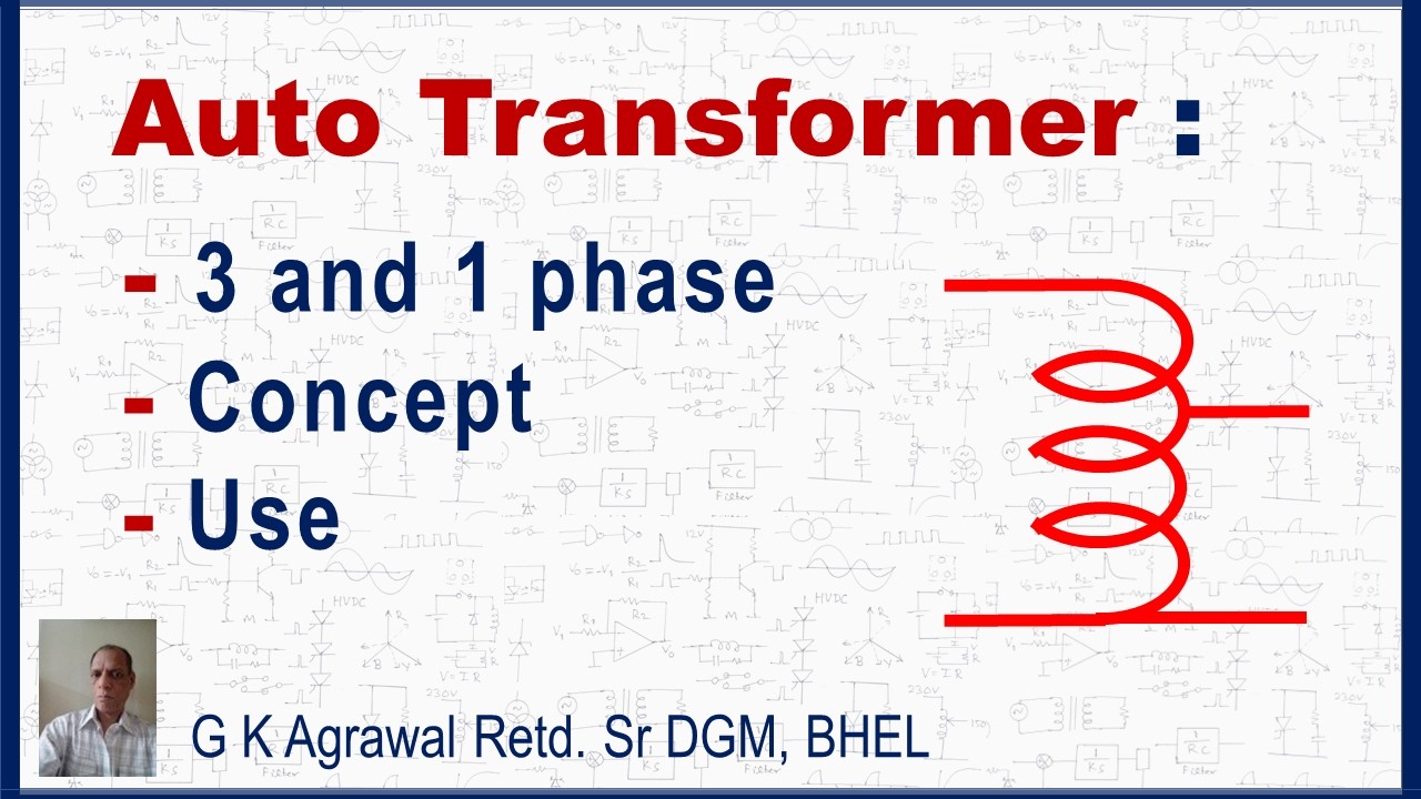
G K Agrawal illustrates the electrical principle discussed here. This background explanation complements the article; it does not demonstrate or authorize field work.
Frequently asked questions
Does an autotransformer provide isolation?
Normally no. Its shared winding creates a conductive connection between source and load. Use an appropriate separate-winding design when isolation is required.
Why is an autotransformer smaller for nearby voltages?
Only part of the through-power is transferred inductively; the shared connection transfers the remainder. The material advantage is greatest when the voltage ratio is close to one.
Can a variable autotransformer provide unlimited current at low voltage?
No. Winding, brush and terminal current limits still apply. Reducing output voltage does not automatically increase permissible current in inverse proportion.
Does an autotransformer change frequency?
No. It changes AC voltage according to its connection and tap while normally preserving source frequency. It is not an AC-to-DC converter.
Why does a motor starter reduce torque as well as current?
Reduced motor voltage reduces electromagnetic torque, approximately with voltage squared in the simplified starting model. The actual load must still accelerate within the permitted thermal duty.