A switchgear interlocking system controls which equipment operations are permitted in defined states. It can use mechanical arrangements, trapped keys, electrical signals or a combination of methods to support an approved operating sequence. Its purpose is to prevent specified incompatible actions; it does not prove that conductors are de-energized or replace safe isolation procedures. Buyers should request a state-and-sequence description for the complete assembly, including interfaces outside the cabinet, and verify that the delivered mechanism, drawings and operating instructions agree. This article is a design-review guide, not instructions for operating energized equipment.
Define the prohibited state first
An interlock specification should begin with the condition that must not occur. Examples at the design-review level include an incompatible position of connected equipment or access that is not permitted in a particular equipment state. The actual prohibited conditions depend on the circuit arrangement and assembly design. Write them clearly enough that an engineer can distinguish a safety-related restriction from an ordinary operating preference. A statement that the cabinet has all necessary interlocks is too vague to verify.
For each restriction, identify the equipment involved, the required information and the consequence of unavailable information. The boundary may extend beyond one cabinet to another device, a remote control circuit or a keyed access arrangement. If the design assumes a signal or physical connection supplied by another contractor, make that assumption explicit. An otherwise correct mechanism can fail to deliver the intended system behavior when the external interface is missing, mismatched or bypassed during installation.
Separate interlocking from isolation
An interlock permits or inhibits an operation according to its design. Isolation for work requires control of the actual energy sources and verification under the applicable safe work procedure. These are related but different responsibilities. A successful mechanical sequence does not establish the absence of voltage. An indication can also be incomplete or incorrect if its supporting mechanism or circuit is faulty. Qualified personnel must use the approved procedure for the actual installation.
Keep this distinction visible in operating documents and training. Avoid wording that implies an unlocked door or released key means every accessible part is safe to touch. The official electrical work-practice reference below provides the framework for distinguishing equipment operation from work on electrical installations. The procurement review should confirm how the interlock system supports the procedure while leaving verification and authorization requirements intact. Equipment features should reinforce those requirements, not conceal them behind an assumption of automatic safety.
Understand the different methods
Mechanical interlocks use physical relationships between mechanisms or positions. Trapped-key systems control a sequence through specified key-release and key-retention conditions. Electrical interlocks depend on the relevant signals, control logic and supply arrangements. A combined design may use one method to establish a state and another to communicate it. None should be selected or evaluated solely from an exterior photograph or a generic description of a product family.
Ask what each method can observe and what it cannot. A mechanical linkage may reflect mechanism position without directly establishing the electrical condition of every conductor. A control signal may depend on auxiliary contacts and wiring. A key sequence may depend on key custody and the absence of unauthorized duplicates. These are review questions for the actual design, not reasons to dismiss a particular method. The important task is to connect each claimed restriction to documented equipment behavior and its supporting interfaces.
Create a state-and-sequence matrix
A matrix makes the intended restrictions easier to review than a list of interlock features. Use the manufacturer’s actual position names and the project’s approved operating states. The following table shows the evidence categories to include; it intentionally does not prescribe a universal switchgear operating sequence.
Reference context: IEC 62271-200 metal-enclosed AC switchgear scope. This original qualitative checklist organizes project decisions; it is not a reproduced standard or a substitute for approved criteria.
| Matrix field | Information to record | Review purpose |
|---|---|---|
| Initial state | Named positions and relevant circuit condition | Establish the starting assumptions |
| Requested action | Exact device movement or access request | Avoid ambiguous commands |
| Permitting conditions | Required positions, keys and verified signals | Identify what enables the action |
| Inhibiting conditions | States that must prevent the action | Define the prohibited combination |
| Interface owner | Supplier of each mechanism or signal | Close gaps between contractors |
| Verification record | Approved test case and observed result | Demonstrate delivered behavior |
Check position language and indication
Terms such as service, test, disconnected and earthed require the definitions for the specific equipment. Similar words can describe different arrangements across designs. Confirm which main-circuit and auxiliary interfaces are connected in each defined position, and how the position is indicated to the operator. The operating manual, drawing labels and cabinet indications should use compatible language. A translation inconsistency can create a practical operating problem even when the mechanism itself is correctly manufactured.
Review abnormal and intermediate states where the manufacturer identifies them. The procedure should explain the relevant restrictions and the response to an uncertain indication without encouraging improvised movement. Operators need a clear path to stop and obtain technical assistance. If a position label is damaged or a mechanism does not behave as documented, treat that as a defect requiring assessment. Do not normalize the condition by adding an informal instruction that contradicts the supplied design.
Resolve the auxiliary-control interfaces
Electrical interlocks require the correct relationship between position signals, control logic and operating commands. The design review should identify signal source, intended meaning, interface responsibility and response to loss of supply or information. Review drawings together rather than approving cabinet wiring separately from the external circuit that completes the function. A terminal number without a signal definition is insufficient for a contractor to verify the intended system behavior.
Changes to relays, auxiliary contacts or control wiring can affect an interlock even when the primary circuit is unchanged. Keep configuration and drawing revisions under control. If the project integrates a remote operating system, distinguish the permissive conditions established locally from those established elsewhere. Remote commands should not be assumed to inherit every restriction automatically. The completed test plan must address the actual interfaces and operating modes, including any modes that are unavailable until another contractor finishes its work.
Treat trapped keys as controlled equipment
A trapped-key arrangement is a system of matched locks, keys and defined release conditions. Request a key schedule linked to the operating sequence and the equipment positions it controls. Identify who holds any spare or emergency keys and what authorization applies to their use. An uncontrolled duplicate can undermine the intended sequence, so key custody should be addressed as part of the operational design rather than as an administrative detail added after delivery.
Do not assume that a key system can be extended by purchasing a visually similar lock. The supplier must assess the complete sequence and compatible components. Changes to the number of access points or interconnected devices need review. During handover, reconcile the delivered key and lock identities with the approved schedule. The owner should have enough records to maintain the system without recreating its logic from labels, memory or the position of keys found during an inspection.
Verify behavior without improvising unsafe tests
Acceptance verification requires an approved method, suitable equipment conditions and qualified personnel. Define the expected outcome of each test before it is performed. The record should identify the assembly, drawing revision, initial state, requested action and observed result. A checkbox labelled interlocks tested does not establish which restrictions were demonstrated or whether an external interface was complete. Factory and site records should make their respective boundaries clear.
Do not test an interlock by forcing a mechanism, defeating a restraint or attempting a prohibited operation outside an approved procedure. This article deliberately does not provide such operating instructions. If a result is uncertain, stop and refer the condition to the responsible technical authority. A defect should be corrected through the manufacturer-supported process and then reverified. Acceptance must not rely on the assumption that the operator will remember an additional caution that compensates for an unresolved equipment discrepancy.
Control bypasses and later modifications
Any exceptional mode provided by the actual design needs defined authorization, restrictions and records. A maintenance or emergency provision should not become the normal method of operation. Ask the supplier how such provisions are identified in the documents and how their condition is restored afterward. The owner must be able to recognize when the intended interlock function is unavailable. Informal bypasses that are absent from the design record leave subsequent operators without a reliable description of the equipment.
Later repairs can also change behavior. Replacing a mechanism, altering an auxiliary contact or modifying an access arrangement requires review of the affected interlocks. Preserve the original logic and the revised acceptance evidence. Train personnel on the final delivered configuration, not an earlier generic manual. Where legacy equipment lacks adequate records, establish a supported assessment rather than copying a sequence from another assembly. Similar exterior cabinets do not prove identical operating relationships.
Write a useful procurement deliverable
For an RFQ, request the state matrix, sequence narrative, interface list, key schedule where applicable and verification plan. Identify who approves them and when they must be available. Require revisions to remain consistent with the single-line diagram, control drawings and operating instructions. This creates a reviewable deliverable before factory acceptance, reducing the chance that important restrictions are first discovered during installation or operator training.
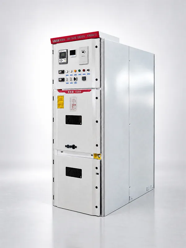
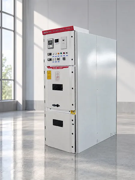
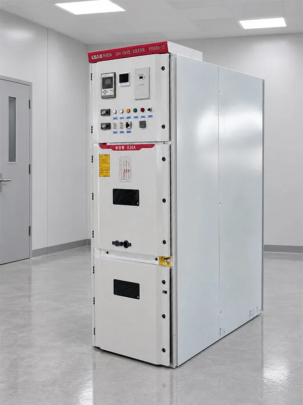
The KYN28A-12 reference images show the actual LBAJI cabinet exterior and visible controls. They do not reveal or certify its internal interlock arrangement. The supplier must establish the functions for the ordered assembly through project documents. Buyers should therefore avoid inferring a five-function or other named interlock claim from the photograph. A clear specification describes the required prohibited states and supporting evidence, leaving the detailed equipment design to the qualified parties responsible for it.
Frequently asked questions
Does an interlock prove that equipment is de-energized?
No. It controls specified actions or states. Electrical isolation and verification for work must follow the approved procedure for the actual energy sources.
Are mechanical and electrical interlocks interchangeable?
Not automatically. They use different information and interfaces. Evaluate the function, restrictions and failure response of the actual complete design.
What is the most useful interlock document for a buyer?
A state-and-sequence matrix linked to drawings, interface responsibilities and an approved verification record makes the delivered behavior reviewable.
Can a spare trapped key be issued without review?
Key custody and permitted exceptional use belong in the approved system arrangements. Uncontrolled duplicates can defeat the intended sequence.
Can an interlock defect be accepted with an operator warning?
An unresolved defect requires technical assessment and a supported corrective decision. An informal warning does not establish that the specified equipment behavior has been delivered.
Technical sources and related equipment
Standard catalogue pages establish document scope; compliance and acceptance require the applicable full documents and project engineering review.
- IEC 62271-200 metal-enclosed AC switchgear scope
- 29 CFR 1910.333 electrical work practices, official 2025 edition
- LBAJI KYN28A-12 Metal-clad Withdrawable AC Switchgear
- switchgear equipment fundamentals
- switchgear verification and testing
- switchgear maintenance checklist
Further learning: equipment functions
This independent educational introduction explains the equipment background. It does not demonstrate a safe work procedure for the specific assembly. Source: Gaurav J – TheElectricalGuy.
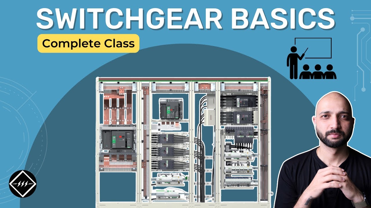
Watch Switchgear Basics: Complete Beginner’s Guide | TheElectricalGuy