Current transformer burden calculation converts the load connected to a CT secondary into a value that can be checked against the selected core’s performance requirements. For switchgear procurement, the useful output is a documented circuit calculation: connected meters or relays, the actual lead arrangement, terminal resistance, selected secondary current and the applicable accuracy requirement. A nameplate VA value alone does not confirm that a complete protection circuit will reproduce fault current correctly. This guide explains a practical calculation and review process for conventional inductive CT circuits; low-power sensors and digital interfaces require their own manufacturer methods.
Start with the circuit function and core identity
Identify whether the circuit supplies revenue metering, operational indication, protection or another approved function. One physical instrument transformer can have separate cores serving different duties. Keep the core number, ratio tap, terminal identifiers and destination device together on the calculation sheet. Otherwise a mathematically correct burden calculation can be attached to the wrong winding.
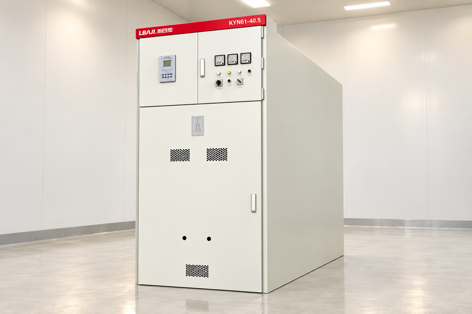
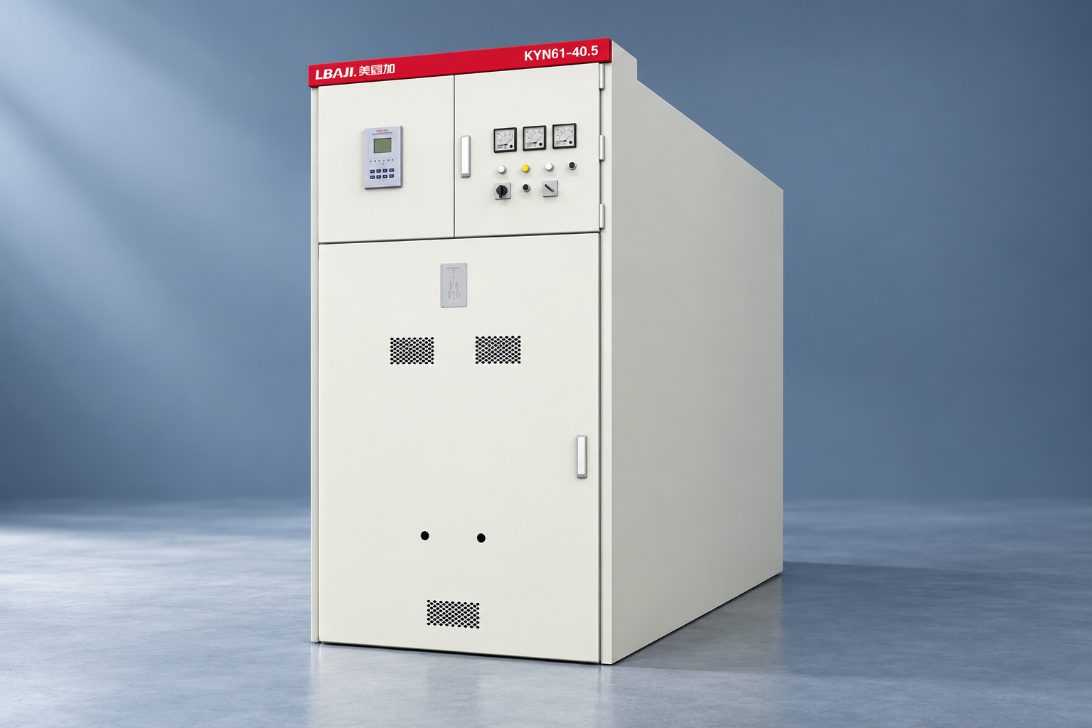
The enclosure photograph does not establish which CT is fitted inside an assembly. For an LBAJI KYN61 switchgear inquiry, request the project instrument-transformer schedule, schematic and offered CT data. The product exterior is a reference for the assembly being discussed, rather than proof of a particular sensor arrangement. Confirm the offered configuration with the supplier before reviewing performance or claiming compatibility.
Establish one consistent electrical basis
For a resistive secondary circuit at rated current, apparent burden is S = I²R, where S is in volt-amperes, I is the rated secondary current in amperes and R is the external circuit resistance in ohms. If an instrument specifies its input in VA at the relevant current, use that value on the same basis. Do not add an input resistance in ohms directly to a burden in VA.
Where the circuit includes significant reactance, use complex impedance or the manufacturer’s specified impedance and power factor. The external burden is distinct from the CT winding’s own resistance. Some protection calculations require both, but adding internal winding resistance to a nameplate external-burden comparison without explanation confuses two different checks. State which calculation is being performed and the governing engineering method.

Build a traceable burden register
Reference context: IEC 61869-2 inductive current-transformer scope. This original qualitative checklist organizes project decisions; it is not a reproduced standard or a substitute for approved criteria.
| Circuit element | Information to collect | Review question |
|---|---|---|
| Connected relay or meter | Input burden at the selected current and applicable frequency | Does the value apply to this exact input option? |
| Outgoing and return leads | Actual route length, conductor resistance and design temperature | Has the complete conducting loop been counted? |
| Terminals and test switches | Approved resistance allowance or supported measured value | Are all series connections represented? |
| Selected CT core | Tap, secondary current, class and rated burden | Are data for the offered core and tap being used? |
| Engineering conclusion | External burden result and separate performance assessment | Is accuracy or protection capability supported beyond arithmetic? |
Use revision-controlled equipment data rather than a generic catalogue from a similar device family. Relay analogue input options can differ, and a future panel extension may change the circuit. The register should identify the document source for each value and who owns unresolved entries. An empty field should remain an explicit action rather than being silently assigned zero.
Count the physical lead loop correctly
For a dedicated two-wire circuit, current travels along an outgoing conductor and a return conductor. If the one-way route is 30 metres, two equal conductors produce a 60 metre conducting path. However, practical three-phase connections and shared returns can require a more detailed circuit model. Use the approved schematic and applicable fault condition; do not impose a universal doubling rule on every connection.
Calculate resistance using supported conductor data at the chosen temperature or the appropriate resistivity method. Include changes in conductor size, junction boxes and marshalling sections. A cable tray distance is not necessarily the installed cable length. Record routing allowance separately from an engineering margin so that a later reviewer can see which part represents physical installation and which part represents uncertainty.
A transparent arithmetic example
Consider a hypothetical conventional 1 A circuit with a complete lead-loop resistance of 0.80 ohm, terminal and test-switch resistance of 0.05 ohm, and a connected relay burden of 0.15 VA at 1 A. The conductor and connection contribution is 1² × (0.80 + 0.05) = 0.85 VA. Adding the relay gives an external burden of 1.00 VA on the stated resistive basis. These are teaching inputs, not KYN61 specifications or acceptance limits.
If a different circuit used 5 A with the same 0.85 ohm external conductor and connection resistance, those components would contribute 5² × 0.85 = 21.25 VA. The relay contribution would still need its own correct 5 A input data; the earlier 0.15 VA must not simply be reused. This comparison shows why secondary current and routing matter, without claiming that either secondary rating is universally preferable.
Separate metering accuracy from protection performance
A metering core must meet the required measurement performance over the project’s specified operating range and burden conditions. Selecting an extremely large ratio to accommodate a speculative future load may weaken useful measurement at normal demand. Likewise, a very high rated burden is not automatically better for every modern low-consumption metering circuit. Check the guaranteed operating range stated for the actual core design.
Protection duties require additional assessment of fault current, saturation behaviour and the relay application. Depending on the governing specification, this may involve accuracy-limit factors, excitation data, knee-point characteristics, transient performance and manufacturer-specific sizing guidance. The burden calculation is an input to that assessment. A result below the rated VA cannot by itself demonstrate that differential or other demanding protection will remain dependable during the relevant fault.
Include temperature and fault-duty assumptions
Lead resistance changes with conductor temperature. State whether the resistance represents a normal operating case, the specified maximum ambient condition or another justified design basis. Keep that choice consistent with the protection method. A supplier should be able to repeat the result using the same assumptions, rather than discovering that one participant used cold conductors and another used a warmer installation.
CT thermal and dynamic withstand are separate primary-side requirements. Do not infer them from the secondary burden result. Likewise, assembly short-circuit ratings and instrument-transformer ratings must each suit their assigned duties. Keep these evidence streams connected through the project schedule, but do not substitute one certificate or a switchgear nameplate for every component-level verification.
Handle multiple devices and spare provisions
Where approved devices are connected in series within the same conventional current circuit, account for each applicable input and every intervening lead section. Confirm that the arrangement is allowed by the protection and metering design. Adding devices without revisiting the circuit can change performance and introduce isolation or test complications. A spare terminal is not evidence of an approved future instrument load.
If future equipment is planned, state its expected input characteristics and connection location. Evaluate a separate future case rather than hiding an arbitrary addition inside the present load. This makes it possible to distinguish an acceptable current installation from an extension that still requires design approval. The handover package should explain what must be recalculated if the circuit changes.
Keep safety outside the spreadsheet shortcut
A conventional CT secondary can develop hazardous voltage if opened while primary current flows. Burden calculations do not authorize live circuit changes, disconnection or improvised testing. Only qualified personnel should use an approved isolation and test procedure with the appropriate equipment. The correct handling of test switches, shorting facilities and earthing belongs in the supplied drawings and work instructions.
The official electrical work-practices source linked below explains the broader requirement to establish safe conditions before work. This article deliberately provides no live terminal-by-terminal manipulation sequence. For a planned secondary-circuit change, the engineering deliverable should include both the revised calculation and a separately approved method that addresses the actual installed arrangement and all possible sources.
Verify the installed circuit against the design
Before acceptance, compare CT identification, tap selection, cable lengths, conductor sizes, terminal arrangements and connected device options with the approved register. Review available test records for continuity, polarity, ratio and other required checks. A burden measurement may support verification when performed under a suitable approved method, but it must be interpreted with the instrument capability, circuit state and connected equipment clearly documented.
Record any difference between calculated and verified values. Investigate the cause rather than increasing the assumed margin until the discrepancy disappears. Excessive connection resistance, a longer route or a changed relay input can each require a different corrective action. Close the evidence trail with an updated drawing and calculation revision, not only an informal statement that the circuit was tested.
Prepare a useful supplier enquiry
Send the supplier the single-line diagram, CT location, core functions, ratios, secondary current, relay or meter input data, route lengths and design conditions. Ask for the offered core data, applicable standard, relevant performance evidence and any exclusions. For existing switchgear, include available nameplate photographs and original drawings; do not guess compatibility from exterior cabinet similarity.
A good quotation response identifies assumptions and unresolved information. If a proposed alternative changes secondary current, core class or terminal arrangement, request a revised circuit assessment before accepting it. Procurement can compare documented alternatives while the protection engineer retains responsibility for the application. This keeps price comparison from concealing a technical change that affects the entire measurement chain.
Frequently asked questions
What is the basic formula for CT burden?
For a resistive external circuit at rated secondary current, S = I²R gives burden in VA. Connected equipment data and any relevant reactance must be included on a consistent basis.
Does a burden below the CT rated VA prove protection suitability?
No. Protection suitability also depends on the fault conditions, CT characteristics and relay application. The external burden is one input to a separate performance assessment.
Should cable length be doubled?
A dedicated two-wire circuit includes outgoing and return conductors. Other connection arrangements require their actual schematic and applicable operating or fault condition rather than a universal shortcut.
Can I use the same relay burden for 1 A and 5 A inputs?
Only if the manufacturer explicitly supports that value for both configurations. Use the data for the exact input and selected secondary current.
Can a switchgear exterior photograph identify the CT core?
No. Obtain the project CT schedule, component identification, schematic and offered data. Cabinet appearance does not establish the internal instrument-transformer specification.
Technical sources and related equipment
Standard catalogue pages establish document scope; compliance and acceptance require the applicable full documents and project engineering review.
- IEC 61869-2 inductive current-transformer scope
- NPTEL current and voltage transformers: CT burden and saturation
- UK HSE HSG85: Electricity at work, safe working practices
- LBAJI KYN61-40.5 Armouring Removable AC Metal Enclosed Switchgear
- switchgear equipment fundamentals
- switchgear verification and testing
- current-transformer fundamentals
Further learning: technical background
This independent educational video explains the measurement principles or equipment background discussed above. It does not demonstrate a safe work procedure for the specific assembly. Source: NPTEL IIT Kharagpur.

Watch Lecture 42: Current transformer and potential transformer